In trolleybus systems of the countries of the former USSR it is used current control. If the trolleybus needs to proceed to the right, then the driver passes the switch with the power circuit turned off. At the same time, a small current flows through the arrow coils, the arrow feathers remain in their original position. When making a left turn, the driver should pass the arrow with the power circuit turned on. As a result, an electrical circuit is created: contact wire (positive) - left arrow coil - left rod - active resistance - right rod - right arrow coil - contact wire (negative). At the same time, both electromagnetic coils are activated and the arrow feathers move to the left direction of movement. They are held in this position until the shoes of both rods pass the arrow. The chain breaks, the coils are de-energized, and the needle feathers, under the action of springs, return to the position for moving in the right direction. In some households, with low qualifications of the operating personnel, this system may have a drawback - the need to turn off the heating, compressor and other secondary consumers when the arrow passes, since they also consume some current, to which a properly working arrow should not respond.
There are also arrows where, to turn in one direction or another, you need to do the opposite, that is, to the left - with an open circuit, and to the right - with a closed circuit. Such arrows are found in the cities of Kyiv, Rivne, Saratov, Dnieper and Ufa.
Has a similar design electric arrow(Selectric switch) in it the contacts are made beveled (usually 45 degrees). In this case, the car passes in the forward direction without switching the arrow, and to switch it makes a sharp turn (usually to the right in countries with right-hand traffic). Due to the bevel, contact closure and switching of the arrow are ensured.
Also applies induction(via transponder) and radio control feathered arrows. In this case, the driver does not need to operate with the passage of current through the power circuit of the machine, which increases the speed of passage through the arrow. Application remote control It also allows you to avoid “cutting” the trolleybus in front by the car following it - the control logic prohibits the translation of the feathers until the rod shoes have passed all the elements of the switch. Often, arrows with a remote contactless drive are equipped with a traffic light to indicate the position of the feathers. This traffic light may also have a stop signal to prevent undercutting. Radio control is carried out using a coded signal; switching occurs when the correct radio code is received. Such arrows were installed in Vologda.
To organize branching in more than two directions, several arrows are installed.
49 ..Guided and similar trolleybus switches
Trolleybus switches are special parts designed to transfer bars from two lines to one common one, and to branch from one direction to two. First view
The arrow is called similar arrows, the second one is called divergent arrows. The design of expendable arrows is more complex than similar ones: to move the bar from one direction, for example to the right or left, the arrow must have a movable feather and a mechanism for translation, while a similar arrow does not need a translation mechanism. The trolleybus driver controls the switch from the cab during movement. In this regard, the name controlled arrows was assigned to consumable arrows.
Depending on the location of the wires forming an angle when approaching the arrow, arrows are distinguished as symmetrical, with each direction deviating by half an angle from the general direction, and asymmetrical, in which one of the directions maintains a straight line, and the second deviates to the right or left by a full angle. The most widespread are symmetrical arrows, the advantage of which is their versatility of use anywhere in the network, ensuring conditions for the passage of special parts by turning at half the angle compared to asymmetrical ones.
Asymmetrical switches have their advantages: better adaptability to traffic conditions in the depot, ensuring preferential passage in the main direction on lines with branches with a low volume of traffic or service purposes, lightening the cable system due to spacer bars or a cross member with a cable guy.
Controlled and similar switches are installed on all branches of passenger lines, on branches from passenger lines to depots and repair shops (factories). In depot areas, settling areas, and areas of repair shops (factories), switches are installed at entrances and exits and on production lines. On the. On branches and rarely used service lines and freight lines, controlled switches are installed only in exceptional cases. The presence of a controlled switch here complicates the movement of passenger transport and causes unnecessary energy consumption for turning on and off the traction motors associated with the passage of the switch. Similar arrows are installed at all junctions for any purpose if the length of the dead-end branch is more than 100 m.
The installation location of the controlled switch on a city street is chosen taking into account the dimensions of the vehicles involved in the traffic. For trolleybuses up to 12 m long, the switch is installed at a distance of at least 20 m in front of the pedestrian path of the intersection, and for articulated trolleybuses this distance is increased to 30 m. The traffic situation is also taken into account. When there is heavy traffic, the controlled switch is moved away from the intersection towards the traffic at a distance that allows trolleybus traffic to be rerouted to the traffic congestion zone in front of the intersection.
In the areas of depots and repair shops (factories), arrows located sequentially in the direction of travel are placed at a distance of at least 8 m. This distance is necessary so that the driver, without stopping movement, has time to change the driving mode (turn on or off the engines).
Arrows are placed on horizontal sections of streets (roads) or longitudinal slopes of no more than 20°/oo. in exceptional cases, under favorable climatic conditions (absence of icy formations with high-intensity winds), installation on slopes up to 30°/oo is allowed.
Switch units have a large mass; a special cross member is mounted to hang each of them. It is possible to suspend two switch units on one supporting cross member, which somewhat reduces the reliability of the network. In this case, the derailment of the rods along the path of one direction causes the arrow of the other direction to oscillate, where, as a result, derailments are also possible.
A controlled switch of the STU-5 type, developed by the Mosgortransniproekt design office, has become widespread in many cities of the USSR. The design is based on the principle of passing meeting centers on the switch and cross plates by sliding the contact insert of the pantograph head, and the divergence angle of the wires in the switch assembly is 25 divided symmetrically by 12 °30" in each direction.
The STU-5 switch assembly is a prefabricated structure (Fig. 94), consisting of two controlled switches, each with one wire (right 8 and left 2), connected by strip insulators, two switching contacts 1, cross 4 with two special strip insulators, three short and three long busbars, sectional insulator 3 brand SI-6DU and sectional insulator 5 brand SI-6U, two electrical jumpers 9, an electrical jumper that passes through the sectional insulators, three end clamps 2, two suspension clamps brand ZPV-2 and bumper 7, which prevents jamming on the crosspiece of the rod during derailment. The arrow is equipped with a symmetry spacer 6, brand RSS-6, which can be replaced with a cross member (symmetry cable) during installation.
Rice. 94. Controlled arrow STU-5

Rice. 95. Arrow controlled by one wire
Each arrow (Fig. 95.) consists of a plate 1, divided into two parts, electrically isolated from each other by an air gap. The mechanical connection of both parts is completed with insulating beams made of wood-laminated plastic DSP-B-E. (At the bottom of the plate there are running elements with beveled ends to facilitate the transition of the pantograph head from one element to another. At the ends of the plate there are holes for fastening the tires and the end part, on the sides there are ears for connecting with strip insulators connecting the right and left arrows, and outside - for the fixing crossbar and anchor branches.The connection of the arrows is quite rigid due to the use of trex insulators of different lengths, one of which acts as a brace, preventing distortions and movements of the arrows relative to each other.
In plan, the switch assembly is fixed by a cross member. To balance the tension forces of two pairs of contact wires extending from the switch and one pair approaching it, anchor branches are connected on both sides from the entrance to the switch assembly. At the top, the plates in its front part install a removable arrow control mechanism 2.

Rice. 96. Pen drive mechanism

Rice. 97. Contact including:
1- contact bracket; 2- long pad; 3- bracket; 4- timber; 5- end clamp; 6- special clamp; 7-element burning
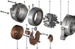
The pen drive mechanism (Fig. 96) consists of an electromagnet, the coil of which is placed in a cylindrical housing. The housing cover 1 is hinged and is an element of the lever system for turning the axis 2, on which two feathers 5 are attached below to move the trolleybus rods to the right or left direction. A return spring 3 is attached to the axis, holding the arrow feather for movement to the right. The tension of the spring is regulated by fixing its end to one or another tooth of the glass 4, in which the axis is placed. The mechanism, together with the feathers, is assembled into a separate removable unit, which is very convenient for replacing it on line, while keeping the pointer unit intact.
One end of the electromagnetic coil wire is connected to the contact on the back of the plate (behind the air gap), the second is electrically connected to the front of the plate. The mechanism is closed on top with casing 3 (see Fig. 95), secured with a wing nut.
When entering the switch, the contact wire is connected by an end clamp to the switching contact (Fig. 97), consisting of two brackets, electrically insulated by an air gap and mechanically connected by insulating bars made of chipboard-B-E, located on the sides of the contact. In front of the air gap on the entrance side there is a burning element (Fig. 98), the purpose of which is to perceive the action of electric arc flashes that occur when the rod crosses the air gap. When an electric arc flashes, the end of the burning element melts, which quite quickly (in comparison with other parts) leads to wear. The burning element is made taking into account the possibility of quickly replacing it and leaving other parts.
The electrically insulated area between two air gaps (one on the switching contact, the second on the plate) is energized by an electromagnet; it is used as a sensor in the switch control circuit.
At the intersection of wires of different polarities, a crosspiece is installed (Fig. 99), which is a frame with running elements in the center of the meeting. The crosspiece is connected to the arrows by long and short running bars and a sectional insulator SI-6DU.

Rice. 98. Burning element
Electrical energy is transmitted bypassing the sectional insulators on the jumper. The crosspiece is protected from lateral movements by two special spacer insulators. To the right, a sectional insulator SI-6U is installed behind the crosspiece. Continuity of the electrical circuit in the isolated direction is ensured through an electrical jumper. The meeting center is the most critical and quickly wearing part; it is made removable, easily replaced and secured to the frame with bolts.

Rice. 99. Arrow cross: 1-- meeting center; 2- frame
The symmetry spacer RSS-6 (Fig. 100) that is included with the switch serves to fix and change the direction of contact wires after passing the switch unit and is a prefabricated structure. Two middle insulating beams 3 made of chipboard-B-E, connected by a clip 4 in the middle, are connected by middle brackets 2 to beams 5. The outer brackets 6 are fixed at the ends of the spacer. Curve holders 7 of grade KD-14 are fixed to each bracket. (In Fig. 100 p: 1 - bending eye.) Due to the smooth bending of the cheeks, a quiet passage of the pantographs along the curved holder is achieved.

Fig. 100. Symmetry thrust point PCC-6
Let's consider the electromechanical circuit of the arrow (Fig. 101). The arrow feather is constantly held by a spring in the direction of movement of the pantograph to the right. When a trolleybus passes the contact zone and the front part of the switch plate with the traction motor turned off, there is a feather on the running line for moving to the right, and the feather for the left direction remains to the side. When passing through this zone with the traction motor switched on, current flows through the electromagnet coil arrows. The electromagnet attracts the armature, overcoming the force of the return spring, moves the feathers, changing their positions: the feather of the left direction is placed on the running line, and the feather of the right direction is moved to the side. The arrow feathers are held in this position as long as current flows through the electromagnet. As soon as the current collector passes the air gap on the plate, the electromagnet coil is de-energized, and the feathers return to their original position under the action of the return spring. Each of the arrows of positive and negative polarity works independently and independently of each other.
The minimum operating current of the transfer mechanism is regulated by the tension of the return spring within the range of 30-90 A; it is selected depending on the current required for trolleybus lighting, compressor operation, interior heating and other trolleybus own needs. To eliminate false switches, the operating current is taken to be slightly larger than the total current for its own needs. If trolleybuses of different types run on the lines, to regulate the switches they take the auxiliary current of more energy-intensive machines (for example, articulated ones).

Rice. 101. Electromechanical diagram of STU-5:
1 - switching contact; 2- feather; 3- electromagnet coil; 4- spring; 5-axis pen rotation
The arrow has an electrified control system with an electromagnetic drive. There are two solenoids in the switch box. They actually have a double core connected to a rod, which, in turn, is connected to the frog feathers (see picture).
The switch control system operates from the tram contact network with a voltage of 600 volts. One of the electric drives is serial ( WITH), it is included in the electrical circuit in series with the tram car circuit. The second is shunt ( Sh) - connected in parallel to the electrical circuit. The series drive is installed in the box arrows on the right in the direction of travel, and the shunt drive is installed on the left.
On the contact wire 16-18 meters in front of the arrow there are serial air contacts ( SK), which lower the arc (pantograph) of the tram, smoothly tearing it away from the contact wire ( KP). 25 meters behind the arrow, in the left direction, at the same level with the contact wire, shunt air contacts are installed ( ShK).
If the tram needs to proceed to the right, then the driver coasts it under serial air contacts, with the engines turned off. Therefore, the arrow remains in the right position, since the serial circuit is open.
If the tram needs to turn left, the driver uses the controller to turn on the engines. When a train passes under serial contacts with the engines turned on, an electrical circuit arises: contact wire - serial electric drive - serial air contacts - car engines - rails - traction substation ( T P/S). At the same time, the serial solenoid drive retracts the core and moves the arrow for the left direction of movement.
After the cars have passed the switch under the shunt air contacts, another electrical circuit automatically arises: contact wire - shunt air contacts - shunt electric drive - rail - traction substation. As a result, the shunt electric drive retracts the core and returns the arrow feathers for the right direction of movement.

Now about trolleybuses
In order for the car to go in the right direction, it is necessary to direct both of its booms in the same direction; this function is performed by the trolleybus switch. When making a left turn, it works on the same principle as a tram: to move left, the driver must pass the arrow with the engine running. But the return of the arrow to the right position occurs not as a result of the action of electromagnetic devices, but under the action of return springs. The operation of a trolleybus switch is much simpler than a tram.
“For decades I have been using the tram - this convenient transport,” writes one of our readers. - In my memory, something like this picture at the tram switch is still alive: a huge mushroom umbrella, a shrunken figure of a switchwoman with a heavy crowbar - a tool for moving the switch. And if for some reason there is no switch operator, the tram stops, the driver jumps out with the same crowbar, moves the switch and, making unflattering remarks about either the weather or the absent switch operator, hurries to the car.
What about now? How do automatic tram switches work? Why, “seeing” an approaching car, does the arrow click in warning, and the tram calmly, without delay, heads in the right direction? Well, of course, nothing supernatural. Apparently the electricity is working. And in that box, in the switch, between the rails, there is probably an electric motor? No, perhaps there is an electromagnetic solenoid, because only it can move the needle so quickly, with one movement. Let's assume this is true. How is the connection between the switch and the car? Obviously, also electricity.
I was so interested in the workings of the arrow that I decided to do some “research”. Indeed, there are wires in the area where the arrow is located. They run to the mast, dive into a metal hose and go down to a small metal cabinet. And under the cabinet you can see the cable. Where is it routed? Maybe to the arrow, it’s very close. Let's say so. I decided to follow the wires. From the mast they scatter in different directions: one along a cable stretched across the street approaches a lantern suspended above the switch; the second is pulled back to some device on the contact wire in front of the arrow. It is very similar to a children's sled, only longer and narrower. There is also a wire - it stretches forward, there, to the left, to a device on a contact wire, very similar to the first skid, only its skids are much thinner. I decided to supplement my “research” with observation of the driver’s actions. I found that if the tram needs to turn left, then, approaching the switch, the driver turns on the control handle for a short time, after which the switch is moved. And when moving to the right, the tram passes the switch with the engines turned off - by inertia, coasting.
The problem begins to become clearer; It turns out that to move right you only need to turn off the engine, and the arrow is already in the “turn right” position. It is clear that to turn left, turning on the engine closes the electrical circuit (the engine is like a switch or switch) and the device (let's say, electromagnets) is activated, which moves the arrow. However, how does the arrow return to the right position again? Doesn't the light, graceful sled play a role here, in front above the arrow, to the left? Having observed carefully, I was convinced that it was precisely at the moment when the tram arc (pantograph) slides along the slide that the arrow returns - it moves to the right.
What voltage is used in all these circuits? Maybe the contact line voltage - I heard it's about 600 volts? But isn't this dangerous for pedestrians?
So, apparently, the principle of operation of the tram switch has been solved. I still wanted to hear confirmation of my thoughts, and at the same time a few words about trolleybus switches. I think that the principle of their operation differs little from the operation of tram switches.”
We asked the head of the Signaling, Centralization, Blocking and Communications Service (SCB and Communications) of the Moscow Passenger Transport Department, engineer B.K. KLESCHINSKY, to talk about the principle of operation of tram and trolleybus switches.
The purpose of the switch is to change the direction of tram trains. This is achieved through the use of special paired wedges - arrow feathers, which press the wheel flanges and direct them in the desired direction.
Manually moving the needle is hard, low-productivity and, in heavy traffic, somewhat dangerous work. Now in Moscow and other cities of the Union the switches are switched automatically. Indeed, the pointer has an electrified control system with an electromagnetic drive. There are two solenoids in the switch box. They actually have a double core connected to a rod, which, in turn, is connected to the frog feathers (see picture).
The switch control system operates from the tram contact network with a voltage of 600 volts. One of the electric drives is serial ( WITH), it is included in the electrical circuit in series with the tram car circuit. The second is shunt ( Sh) - connected in parallel to the electrical circuit. The series drive is installed in the box arrows on the right in the direction of travel, and the shunt drive is installed on the left.
On the contact wire 16-18 meters in front of the arrow there are serial air contacts ( SK), which lower the arc (pantograph) of the tram, smoothly tearing it away from the contact wire ( KP). 25 meters behind the arrow, in the left direction, at the same level with the contact wire, shunt air contacts are installed ( ShK).
If the tram needs to proceed to the right, then the driver coasts it under serial air contacts, with the engines turned off. Therefore, the arrow remains in the right position, since the serial circuit is open (diagram 1).

If the tram needs to turn left, the driver uses the controller to turn on the engines. When a train passes under serial contacts with the engines turned on, an electrical circuit arises: contact wire - serial electric drive - serial air contacts - car engines - rails - traction substation ( T P/S). In this case, the serial solenoid drive retracts the core and moves the arrow for the left direction of movement (diagram 2).

Thus, the tram train controller serves as a kind of switch that closes the serial electrical circuit of the switch. After the cars have passed the switch under the shunt air contacts, another electrical circuit automatically arises: contact wire - shunt air contacts - shunt electric drive - rail - traction substation. As a result, the shunt electric drive retracts the core and returns the arrow feathers for the right direction of movement (diagram 3).

To protect electrical circuits, a switching cabinet with fuses and disconnecting devices is installed on the support or wall of the building closest to the switch. It is this device that the attentive reader noticed on the mast.
Finally, there is the issue of safety. For pedestrians, the described switch control system is completely safe; all devices located at a height accessible to pedestrians are isolated and reliably grounded. The turnout drive devices have direct and reliable contacts with the rails, to which are connected “suction” (negative) feeders going to the traction substations. As a result, the potential on the rails is usually no more than 10-15 volts.
Now about trolleybus switch. In order for the car to go in the right direction, it is necessary to direct both of its booms in the same direction; this function is performed by the trolleybus switch. When making a left turn, it works on the same principle as a tram: to move left, the driver must pass the arrow with the engine running. But the return of the arrow to the right position occurs not as a result of the action of electromagnetic devices, but under the action of return springs. The operation of a trolleybus switch (see diagram below) is much simpler than a tram switch.
 .
.
The arrow consists of two halves installed on the wires of the trolleybus contact network. These halves, isolated from each other, each have an electromagnetic coil ( EM). When triggered, they deflect their arrow feather to move in the left direction. The driver of the car, wanting to make a left turn, passes under the arrow with the engine turned on, and as a result an electrical circuit is created: contact wire (positive) - left coil of the arrow - left rod - trolleybus engine ( D) - right rod - right coil arrows - contact wire (negative). At the same time, both electromagnetic coils are activated and the arrow feathers move to the left direction of movement. They are held in this position until the shoes ( B) both rods will not pass the arrow. The chain breaks, the coils are de-energized, and the needle feathers are under the action of springs ( ETC) return to the position for driving in the right direction. The arrow operates from a contact network with a voltage of 600 volts.
© 1967, Science and Life magazine. © 1999, Alexander Elagin
Trolleybus switch STU-5, typical for systems of the former USSR
Trolleybus switch- a mechanism that guides trolleybus rods in places where the contact network branches.
The peculiarity of the rod pantograph is that the pantograph shoe is guided by a contact wire. In order for the machine to go in the desired direction, it is necessary to point both of its rods in the same direction.
Device [ | ]
The arrow consists of two halves mounted on the wires of the trolleybus contact network. These halves, isolated from each other, each have an electromagnet, which, when triggered, each deflects its arrow feather. There are various circuits for controlling electromagnets.
Varieties [ | ]
Turnout switch for trolleybus contact wire

Double turnout

Turnout at the intersection of contact lines

Arrow with direction indicator
In trolleybus systems of the countries of the former USSR it is used current control. If the trolleybus needs to proceed to the right, then the driver passes the arrow with the switch turned off. At the same time, a small current flows through the arrow coils, the arrow feathers remain in their original position. When making a left turn, the driver should pass the arrow with the power circuit turned on. As a result, an electrical circuit is created: contact wire (positive) - left arrow coil - left rod - active resistance - right rod - right arrow coil - contact wire (negative). At the same time, both electromagnetic coils are activated and the arrow feathers move to the left direction of movement. They are held in this position until the shoes of both rods pass the arrow. The chain breaks, the coils are de-energized, and the needle feathers, under the action of springs, return to the position for moving in the right direction. In some households, with low qualifications of the operating personnel, this system may have a drawback - the need to turn off the heating, compressor and other secondary consumers when the arrow passes, since they also consume some current, to which a properly working arrow should not respond.
There are also arrows where, to turn in one direction or another, you need to do the opposite, that is, to the left - with an open circuit, and to the right - with a closed circuit. Such arrows are found in the cities of Kyiv, Rivne, Saratov, Dnieper and Ufa.
Has a similar design electric arrow(Selectric switch) in it the contacts are made beveled (usually 45 degrees). In this case, the car passes in the forward direction without switching the arrow, and to switch it makes a sharp turn (usually to the right in countries with right-hand traffic). Due to the bevel, contact closure and switching of the arrow are ensured.
Also applies induction(via transponder) and radio control feathered arrows. In this case, the driver does not need to operate with the passage of current through the power circuit of the machine, which increases the speed of passage through the arrow. Application