The modification range of the VAZ 2106 family includes:
- VAZ 2106, 21065-00 - equipped with a model 2106 engine;
- 21061, 21065-01 - equipped with a model 2103 motor;
- 21063 - there was an engine from 21011.
- Car brand 21065 is a luxury variant of this family. It has the following differences from the 2106 model: equipped with a five-speed gearbox and final drive with a gear ratio of 3.9. Some cars were equipped with a Solex carburetor and a contactless ignition system. The electrical equipment of the car is supplemented by an electrically heated rear window, halogen headlights and an anti-fog taillight. The body has been modified: the upholstery and headrests of the seats have been updated; the car is supplemented with model 2105 bumpers. Spare parts for the presented vehicles are everywhere. In addition, a kind of "novelty" is, so to speak, the trends of the 21st century make themselves felt. Thanks to this, car maintenance and repair is not a big problem.
Ignition scheme VAZ 2106
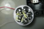
Includes ignition distributor, coil, spark plugs, lock, and low and high voltage wires. The connection diagram of the VAZ 2106 of this car system is shown in the photo.
- Until 1980, machines of this brand were equipped with the R-125B distributor. It was installed in conjunction with 2103 type carburetors. This distributor had a mechanical octane corrector, with which it was possible to slightly change the ignition timing, however, at the same time, there was no special vacuum regulator. After 1980, when the engines were equipped with carburetors 2107-1107010-20 ("Ozone"), they began to use the distributor 30.3706, which had a vacuum ignition timing controller.
- The coil used was of type B117-A. There was an open magnetic circuit. The device is oil-filled, sealed.
- Candles of the A17DV type or similar ones, but of foreign production, were used.
- Cars were equipped with a VK347 lock, which had an anti-theft device. It works as follows: when the key is removed (from position III "Parking"), the locking rod is pulled out of the switch body in a special way. It enters the groove of the steering shaft and, thus, the shaft is blocked.
It is recommended that you always carry with you, if you are the owner of a car 2106, an ignition distributor capacitor and an ignition coil. The probability of their failure is quite high, it is impossible to replace or repair them using some other devices.
If the coil or capacitor is damaged, it will be impossible to start the engine, but replacing failed devices is very simple. For example, the ignition switch (shown in the video). If an emergency arises, they can be replaced with similar devices from other car models.
Scheme of electrical equipment VAZ 2106
The electrical circuit of the VAZ 2106 is a detailed "plan" on the basis of which the entire electrical connection system of the car operates. It consists of:
1 - front lights; 2 - side direction indicators; 3 - battery; 4 - relay from the battery charge control lamp; 5 - relay, which turns on the dipped headlights; 6 - relay for high beam headlights; 7 - car starter; 8 - generator; 9 - lighting devices (headlights) of high beam; 10 - low beam devices; 11 - sensor, which is used to turn on the fan motor; 12 - electric motor of the SOD fan (engine cooling system); 13 - horn (beep); 14 - ignition coil; 15 - incendiary distributor; 16 - spark plugs; 17 - carburetor solenoid valve; 18 - a sensor that shows the temperature of the coolant; 19 - engine compartment lamp; 20 - car reversing light switch; 21 - a sensor showing the level of oil pressure; 22 - oil pressure sensor; 23 - sensor from the control lamp, indicating the level of brake fluid; 24 - an electric motor that is used by a windshield cleaner; 25 - switch (supplied if a contactless ignition system is used); 26 - electric motor from the windshield washer; 27 - fan motor relay; 28 - machine voltage regulator; 29 - a special relay-breaker for the windshield wiper; 30 - a special additional fuse box; 31 - main fuse box; 32 - relay-interrupter of the automobile alarm system and the corresponding direction indicators; 33 - relay, which turns on the rear window heater; 34 - stoplight switch; 35 - a special socket for a transport personal lamp (not installed since 2000); 36 - a special additional resistor of the car electric motor of the heater; 37 - electric motor, without which the operation of the heater is impossible; 38 - obligatory heater motor switch; 39 - machine clock; 40 - a lamp that illuminates the glove box; 41 - auto cigarette lighter; 42 - alarm switch; 43 - a special lighting controller for transport devices; 44 - a control lamp, which symbolizes an insufficient level of brake fluid; 45 - light switch for headlights, sound signals and direction indicators; 46 - car ignition switch; 47 - switch for the engine rear window heater; 48 - switch for the rear fog lamp of the car; 49 - outdoor lighting switch VAZ 2106; 50 - door light switches (front pillars); 51 - electric window motor (it is equipped with some of the manufactured vehicles); 52 - door light switches (rear pillars); 53 - switch of the control lamp of the automobile parking brake; 54 - ceiling lamps that produce interior lighting; 55 - fuel gauge in the car, which has a reserve control lamp; 56 - indicator of the temperature state of the coolant; 57 - oil pressure indicator, equipped with a warning lamp for insufficient pressure; 58 - automobile tachometer; 59 - control lamp (CL) of the parking brake; 60 - CL battery charge; 61 - KL carburetor air damper; 62 - KL side light; 63 - KL turn indicators; 64 - KL high beam headlights; 65 - autospeedometer; 66 - switch KL carburetor air damper; 67 - "left-door" switch of the electric motor of the power window; 68 - automotive power window relay; 69 - "orthodox" electric window motor switch; 70 - rear transport lights; 71 - lights that illuminate license plates; 72 - sensor showing the level and reserve of fuel; 73 - rear window heater; 74 - a lamp with which the trunk is illuminated; 75 - rear transport fog lamp.
Fuse diagram VAZ 2106
The VAZ 2106 fuse circuit is one of the simplest. It presents two lines with automotive fuses. This design is fastened with two nuts to the machine body. If you need to remove the fuse line, you will have to disconnect the battery. The disadvantages of this in its uncomfortable lids.
The main disadvantage is that due to the unbending legs, contact sometimes disappears. And in some cases, due to poor contact, the fuse heats up and, as a result, the plastic ruler melts. This disadvantage can be easily corrected by replacing the fork-shaped fuse box. It will take 10 minutes, but in the future, thanks to this “”, you will get rid of various troubles that are associated with electricity.
In detail: do-it-yourself wiring repair vaz 2106 from a real master for the site site.
Version 24.10.16 beta
Website moving to a new domain.
The electrical circuit of the car VAZ 210 6
a - switch;
b - ignition distributor sensor;
c - windscreen cleaner and windshield cleaner breaker relay;
g - relay of the alarm breaker and direction indicators;
e - three-lever switch.
* It is installed in case of using a non-contact ignition system on the car. In this case, an ignition distributor type 38.3706 and an ignition coil type 27.3705 or 027.3705 must be installed.
** Since 2000, it has not been installed and the electric motor 12 is switched on directly by the sensor-switch 11. In this case, instead of the previously used temperature sensor 11 of the TM-108 type, the sensor-switch 661.3710 is used.
*** Installed on car parts.
**** Not installed since 2000.
The order of conditional numbering of plugs in blocks:
a - windscreen cleaner and windshield cleaner breaker relay;
b - alarm interrupter relay and direction indicators;
c - three-lever switch.
* Installed on parts of manufactured cars.
A typical wiring diagram for the VAZ 2106 is made taking into account the single-wire principle of connecting elements of the vehicle's electrical equipment. This means that the negative contacts of electronic devices are brought to the so-called. "mass" of the vehicle, and the wired connection provides only positive terminals.
This principle of integrating electronic components into the electrical circuit of a car is put into practice in the following form of connections:
- The operating electrical circuits of the vehicle are activated by using the ignition switch.
- Electronic devices that ensure the maintenance of the required degree of safety during vehicle operation are connected to the battery through a safety block.
- The body parts of all the six units are good current conductors.
Important: when carrying out maintenance and repair work on a car, it is necessary to de-energize the electrical wiring by removing the negative wire from the battery terminal, otherwise unauthorized touching of the battery contact with the tool may lead to a short circuit. For clarity, the diagram e. VAZ 2106 wiring is posted on our Internet resource, and motorists can use it to conduct the necessary tests.
With self-maintenance of the vehicle, it is necessary to determine the cause of a defect in the electrical components of the "six". Troubleshooting should begin with the ignition switch, which is designed to:
- management of the functionality of the ignition system;
- coordinating the work of security systems and preventing car theft;
- towing "six" with a working "emergency gang".
In a VAZ 2106 car, the wiring diagram includes the following elements:
- Battery with a negative wire contact on the vehicle body;
- starter with connector "50" from the ignition switch through the start relay;
- generating device;
- safety block;
- ignition switch;
- control relay.
The ignition switch has 4 positions, when each of them is activated, certain connectors and contacts are switched:
- In the "0" position, the battery current is transmitted only to connectors 30 and 30/1, the others are de-energized.
- In the “I” position, the current is supplied to the connectors 30-INT and 30/1-15, while the “dimensions”, the windshield wiper, the fan heating system of the heating complex are under voltage.
- In position "II", contact 30-50 is additionally connected to the previously used connectors. In this case, the ignition system, starter, panel sensors, "dimensions" and "turn signals" are included in the circuit.
- In position "III", only the "dimensions", the horn and the windshield and rear window wipers are activated. In this case, the current is available only to the 30-INT and 30/1 connectors.
A number of cars of this brand are equipped with such devices as a heating system for the rear window, an electric windshield washer, a light relay, etc. The power supply to these gadgets is supplied through a separate line through the ignition switch at key positions "I" and "II".
Important: because Since the washing tank is made of PVC material and is a dielectric, the electric motor is additionally equipped with a negative wire and when working with it, it is necessary to use dielectric protection on the connectors.
In the "six" under current, the following power circuits operate in a constant mode: a horn, brake lights, an emergency gang, a cigarette lighter socket, a "carrying" plug, and instrument lighting. The leading circuits of the electrical equipment of the transport are subject to protection by fuses, which are located in two special blocks (main and spare) located on the driver's side under the dashboard.
One of the elements of the VAZ 2106 wiring diagram is a safety block, the design of which does not meet modern requirements for the maintenance of electronic equipment. Flaws:
- unstable connection of the fuse and the socket leads to the appearance of burning places;
- during operation, the safety element is subject to heating, which negatively affects the nearby mounting sockets;
- the low cost of replacement fuses does not guarantee their reliability, so checks on this unit should be carried out regularly.
The use of the so-called. "bugs" can lead to a vehicle fire, because. there is a high probability of a short circuit. There is a completely safe option for upgrading standard products, in which blade fuses are to be installed, the seats of which are perfectly integrated into the fuse block.
Benefits of knife fuses:
- stable contact of the product with the place of attachment;
- the fusible type element is sealed in a transparent PVC case;
- dynamic heat dissipation due to the increased contact area.
Important: the “six” generator device, the wiring to it, as well as to the battery, starter, bobbin, optics switching relay and some other elements are not equipped with safety elements.
The diagram of the electrical equipment of the VAZ-2106 machine is necessary for troubleshooting electrical wiring and their quick elimination.
The entire complex of electrical equipment is connected in a single-wire type - the negative terminals of the outputs from the current sources are connected to the “ground” directly to the element that consumes energy. As a result, the “mass” in this VAZ-2106 circuit acts as the second connecting wire. The figure below shows a complete view of the vehicle equipment and wiring diagram.
Full view of the scheme of equipment and wiring VAZ-2106
The VAZ-2106 circuit at the level of electrical equipment is especially useful for the owners of this car when it becomes necessary to quickly troubleshoot the electrical wiring system. Have you adjusted the valves on the VAZ-2109? Check the wires!
In addition, the circuit is often used to evenly connect additional elements and audio devices. If you decide to replace or repair lighting fixtures, the ignition system and other electrical equipment on the VAZ-2106, using this diagram you will find the desired terminal and current source. If problems are found with the engine, first check the torque of the cylinder head bolts, and then check the wiring.
Consider this wiring plan in parts, in which specific parts and elements of the electrical equipment of the machine will be painted.
This diagram allows you to consider the elements of the front of the machine. Here are:
- Side left and right direction indicator (1);
- Several sidelights (2);
- External (3) and internal (4) samples of headlights;
- Connected horn (5).
- Terminals of the electric motor of both fans included in the cooling system of the VAZ-2106 engine (6);
- A set of sensors responsible for the timely switching on of the electric motor (7);
- 2 types of relay - one is used when turning on the sound signal (8), and the other when regulating the operation of the electric motor of the cooling system (9);
- Small voltage regulator in the car (10);
- Car ignition coils (11);
- 2nd electric motor, which is responsible for the operation of the windshield washer (12);
- One of the main sensors of the VAZ-2106 - it determines the level of brake fluid in the car and in a timely manner gives the owner a command about non-compliance with the established standards (13);
- Also in the center of the diagram are the distributor of the ignition system (14) and the engine for the windshield wiper (15).
The following electrical equipment completes this part of the circuit:
- Set of machine spark plugs (16);
- Sensors monitoring the oil mixture pressure lamp (17) and a gearbox with an indicator of this pressure on the panel (18);
- Also shown is the connection of the current temperature indicator sensor in the engine coolant (19) and the engine compartment lamp VAZ-2106 (10).
Advice: If you have problems with the operation of the engine and specifically the running gear, first check the pressure in the tires of the car using the table - are all the wheels properly inflated? Then start investigating wiring problems!
This part of the diagram shows the elements and spare parts responsible for the operation of the engine and the electrical wiring system (starters, relays, etc.). When viewed from top to bottom, you can see the following elements:
- Carburetor solenoid valve kit (21);
- The design of the car generator (22) and the starter itself (23);
- Battery terminals (24);
- A set of various types of relays responsible for receiving a charge for the entire system from batteries (25), turning on headlights with low beam (26) and high beam (27), as well as a relay that controls the operation of the wiper (28);
- At the end, the connection to the additional fuse box (29) is indicated.
The central piece of the circuit mainly consists of on / off switches for lighting and switches for supplying current to the system. The main wiring elements are indicated by the following numbers:
- Kit with main fuse box (30);
- Light switches in the reversing headlights of the machine (31), operation of control lamps when the hand brake is applied (32);
- Varieties of socket outlets for portable lamps (33);
- Equipment for the operation of the turn signal indicator and emergency signal (34);
- The design of the electric motor of the stove (35) and terminals for turning off the operation of the brake light (36);
- Current supply relay for heating the rear window (37);
Advice: depending on the modification and year of manufacture of the VAZ-2106, the type of relay and its position in the network may change. To repair this part, it is best to use the diagrams that come with the machine.
- Set of resistors for the electric motor of the stove VAZ 2106 (38);
- Wiring to the light bulb in the glove box (39);
- List of outdoor light switches (40), heating the rear surface of the glass (41), as well as the ignition system (42);
- Set of switches from dipped to high beam (43), wiper (46) and arrow-indicator of the direction of the car (44);
- Special types of car horn switches (45), universal windshield washer (47) and dashboard light and emergency horn switches.
The electrical wiring of the machine is protected by fuses, which are mainly installed in the central and auxiliary unit located at the bottom of the instrument panel on the left side next to the steering column. The circuit from the battery to the terminals and partings closes when the ignition is turned on by the car.
Advice: When carrying out work on replacing or repairing lighting fixtures and wiring, be sure to disconnect the battery from the mains. Relays, switches, batteries, spark plugs, and even the relay winding in the lighting and fan switching system in the cooling system are not protected by fuses. When the brakes are bled on the VAZ-2107, a similar problem may arise.
If one of the circuit elements is damaged, the fuse is activated. In the event of a malfunction of the main set of fuses, backup fuses are activated, which are additionally installed next to the ignition unit. If a blown fuse is found, it is not enough just to replace it - you need to study the wiring in detail and find out the reason for the combustion of this spare part in the VAZ-2106.
The electrical equipment and wiring diagram should help you quickly find and fix faults in the headlights, dashboard indicators and other systems of your VAZ-2106.
As you know, the electrical circuit in any vehicle is one of the main components. The electrical equipment diagram allows the driver of the VAZ 2106 to correctly identify system malfunctions when equipment malfunctions are detected. This article is devoted to the wiring of domestic "sixes".
Domestic yellow "six"
Regardless of which ignition scheme in your VAZ 2106 is contact or non-contact (cc), the vehicle's electrical circuit includes the following components:
- battery with a negative contact on the car body;
- starter device with output "50";
- generator - one of the main elements of the VAZ 2106 electrical circuit;
- mounting block with fuses protecting power supply circuits;
- ignition switch;
- regulator relay.
It should be noted that the electrical circuit of the VAZ 2106 car with or without BSZ was initially made taking into account the single-wire type of connection of electrical equipment components. In fact, this means that the negative contacts of electrical equipment are brought to ground, that is, the vehicle body. As for the wired connection, it is provided exclusively by positive wiring.
Wiring diagram on the "six"
If you have to look for a wiring malfunction on the VAZ 2106, during the repair work it is necessary to completely de-energize the electrical circuit. To do this, you will need to disconnect the negative wire from the battery terminal, otherwise a short circuit may occur in the VAZ 2106 electrical circuit. Diagnostics of breakdowns is detected using the scheme above.
If there are interruptions in the wiring, there are several options for the car to behave in this case:
- The car cannot move and will not start. There can be many reasons for possible malfunctions, but first of all, it is necessary to check the starter, distributor, battery performance. As a rule, a complete discharge of the battery is one of the most common causes. The generator fails much less often, but attention should also be paid to the diagnosis of this element on the VAZ 21062 with BSZ.
- The machine moves, but one or more electrical components are not working properly. For example, these may be malfunctions in the operation of the interior light, turn signals, rear window heating or optics. If this is the case, then first of all it is necessary to check the fuse box and identify burnt out elements. If all the fuses are intact, then in the case of optics, the operability of the lamps is first checked, after which the wiring of the VAZ 21063 machine is checked with or without BSZ.
- controls all the possibilities of the ignition system;
- manages the work of security and anti-theft systems VAZ 21063;
- allows towing 21063 with a working light alarm (video by Andrey Aleksandrov).
The ignition switch on 21063, in accordance with the diagram, has four modes, when each of them is turned on, certain equipment is activated:
- In mode 0, the pulse from the battery comes only to two connectors - 30 and 30/1, the rest of the connectors are de-energized.
- In mode 1, a pulse begins to be applied to other connectors, as a result of which the side lights, glass wipers, fan, and the rear window heating device can work.
- In mode 2, the circuit includes the ignition system, gauges on the dashboard, turn lights, and the starter.
- In mode 3, only side lights, steering horn, and glass cleaners work.
In constant mode, under current in model 21063, in accordance with the scheme, the steering horn, brake lights, light signaling, lighting on the control panel, and the cigarette lighter work. The main elements of the circuit are protected by fuses located in the main and additional blocks installed under the instrument panel opposite the driver's seat (the author of the video is Vyacheslav Viter).
In order to correctly replace the necessary circuit elements, the following procedure must be carried out in the event of a malfunction.
Such actions are relevant if the car refuses to start:
- Check the battery. Perhaps he was just exhausted.
- First of all, the section on the circuit from the generator device to the coil is checked. If there are breaks in the circuit, new wires are replaced and connected, oxidation - cleaning of contacts using an iron brush. If the contacts began to "crumble", they must also be replaced.
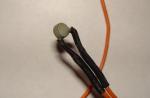
- Check the coil for spark. Remove the high-voltage cable from the installation site and bring it to the car body. When you try to start the engine, a spark should jump between the high voltage and the body.
- Check if the spark plugs are working. It happens that the reason for the impossibility of starting the engine is the soot formed on the candles. You can easily clean them on your own, for this you need to remove the candles and follow the instructions that you will find here.
- Poor connection of the fuse itself with the seat, which leads to burning of the sockets.
- During operation, auto fuses always heat up, as a result of which they also negatively affect the sockets located nearby.
- The unit must be checked regularly, since the cost of fuses is always low, and this corresponds to not very high quality of their workmanship and reliability.
Sorry, there are currently no surveys available.
The detailed designation of the fuses on the "six" is described in the video below (the author of the video is AVTOCLUB_22).
On VAZ 2106 vehicles, the wiring diagram includes more than ten different components and modifications of the general network. The owner of the machine needs to understand this issue in order to repair and diagnose the electrical network if necessary.
Let's start with a description of the designations of the general wiring diagram and equipment of the VAZ 2106:
Below are the wiring diagrams for the VAZ 2106 in color photos and pictures. Each system is equipped with an electrical plan that allows you to connect wires and connect electrical appliances.
Designation of wiring components of the generator set:
- 1 - battery;
- 2 - generator set "six";
- 3 - regulatory device designed to control the operating voltage parameter;
- 4 - lock;
- 5 - plastic module with safety elements;
- 6 - control light indicator that determines the charge of the battery;
- 7 - a relay that protects the power line of the control light indicator of the battery charge.
The wiring of the "six" to start the power unit is tied to the starter assembly:
- 1 - car starter device;
- 2 - battery;
- 3 - generator set;
- 4 - ignition lock.
The symbol P1 denotes the retracting winding of the relay, and the symbol P2 denotes the holding one.
Depending on the modification, the domestic "six" can be equipped with a contact or non-contact ignition system. Both options have certain differences, indicated in the above diagrams.
- 1 - spark plugs;
- 2 - distributor;
- 3 - ignition switch;
- 4 - coil;
- 5 - switch;
- 6 - generator;
- 7 - battery.
- 1 - battery;
- 2 - generator;
- 3 - ignition switch;
- 4 - coil;
- 5 - switch;
- 6 - sensor-distributor;
- 7 - candles.
- 1 - end switching device of the carburetor unit;
- 2 - directly the engine valve itself;
- 3 - a module used to control the carburetor assembly;
- 4 - ignition coil;
- 5 - switching device;
- 6 - ignition switch, is a lock.
- 1 - lighting devices for turning lights installed in the front optical devices;
- 2 - battery;
- 3 - auto generator unit;
- 4 - side turning lights located on the front fenders;
- 5 - main mounting module with safety elements;
- 6 - auxiliary control unit with safety devices;
- 7 - ignition switch;
- 8 - a device for turning off and activating the light signaling, mounted in the car on the center console;
- 9 - switching device for activating and deactivating turning lights;
- 10 - interrupting device used for flashing turning lights and signaling lights;
- 11 - speedometer equipped with a control light indicator for the activation of turning lights;
- 12 - lighting devices for indicators of turning lights in the rear optics.
Description of the main elements of this component of the electrical circuit:
- 1 - sound devices used to reproduce impulses;
- 2 - a relay for activating sound impulses, protects the electrical circuit from overvoltage;
- 3 - switch of sound impulses;
- 4 - mounting module with safety elements;
- 5 - generator set VAZ 2106;
- 6 - battery.
Designation of the elements of the activation system of the electric motor of the heating unit:
- 1 - electric motor of the heating system;
- 2 - additional resistor element;
- 3 - switching device of the electric motor of the stove in the car;
- 4 - safety module;
- 5 - lock;
- 6 - generator unit;
- 7 - battery.
Various modifications of the VAZ 2106 can be equipped with additional electrical equipment. In this case, the wiring is laid additionally, and the general circuit is equipped with other components.
- 1 - main safety module;
- 2 - a relay used to protect the power line of additionally installed power windows;
- 3 - switching device of the power window mounted on the left door;
- 4 - a similar device used to adjust the position of the glass in the right door in front;
- 5 - electric motor of the left glass lift;
- 6 - auxiliary module with safety elements;
- 7 - ignition lock.
Terminal A is connected to terminal 30 on the generator set, terminal B is connected to the switchgear of the panel lighting system. Output B is a shorthand for the connectors in the system's motor block.
The Vvideo video channel demonstrated the procedure for installing and connecting power windows on the VAZ 2106.
The modified version of the carburetor valve control circuit has several differences:
- 1 - ignition switch or lock;
- 2 - generator set for supplying equipment with voltage;
- 3 - battery;
- 4 - ignition coil;
- 5 - switching unit located in the engine compartment;
- 6 - control module;
- 7 - the valve of the carburetor installation itself;
- 8 - limit switch of the carburetor device.
- 1 - generator unit, installed under the hood;
- 2 - battery;
- 3 - ignition switch or lock;
- 4 - main module with safety elements;
- 5 - a relay that protects the power line of the activation system for the electric motor of the cooling fan of the power unit;
- 6 - ventilating device activation controller;
- 7 - the fan itself;
- 8 - auxiliary safety module.
The "Six" is equipped with a safety module, the designations of its components are given below.
User Ramanych clearly showed how to replace the safety element pads on the "six".
The main feature of the VAZ 2106 electro wiring is that it is single-wire. Therefore, it is interesting to look at the wiring, which performs 2 roles: plus and minus. It is also important to know that everything that is electrical in the car is designed for a specific workflow.
As for the car itself, many are already familiar with the functionality of the VAZ 2106 car, the space both under the hood and in the trunk. This car can be customized as soon as the user is comfortable. But even such a famous car as the VAZ 2106 can again surprise with something.
Wiring elements, like any other element that is responsible for the functioning of the car, has its own characteristics in full, and the wiring diagram, in turn:
- activates electrical circuits by using the ignition switch VAZ 2106;
- connects to the battery through the fuse box;
- conducts electric current of key nodes.
Based on all of the above, you need to start looking for all malfunctions from the ignition switch, because most of the responsibility lies with it. The key node itself is not only responsible for controlling the entire ignition system in the car, but also performs a security function. It also allows the car to be towed.
The ignition lock of such a classic car as the VAZ 2106 has 4 modes of operation, which differ in the performance of electrical functions.
- Zero mode is practically not responsible for anything, it only feeds some wires.
- The first mode makes it possible to function not only running lights, but also fog lights, wiper blades and supports the heating of the car.
- The second mode is responsible for the operation of the turn signals, dashboard and ignition system.
- The third position feeds the terminals.
Replacing the ignition switch may be necessary one day for almost every driver. This can be explained by the fact that some drivers lose their ignition keys, but how to start a car without keys?
Well, if we talk about a classic car, most likely, the driver of the VAZ 2106 has already dealt with the physical wear and tear of some parts, in this case we are talking about the lock cylinder. If the wires in the ignition already look somehow suspicious, then in this case, the wiring must be replaced as soon as possible so as not to lead the situation to a short circuit.
In order to replace the ignition switch, you must perform the following steps:
- disconnect the battery;
- unscrew all the screws of the casing under the steering wheel and remove it;
- move the key node to position "0";
- insert the awl into the hole to remove the latch;
- mark the contact wires so as not to confuse them in the future;
- install a new lock and follow the instructions again, but vice versa.
It is convenient that the wiring diagram is made in such a way that in order to change the entire contact group, the ignition switch does not need to be removed at all. But in any case, you don’t actually need to “rip off” everything with one hand, because you won’t be able to install everything that was previously removed back.
As for the purchase of spare parts, in this case it should be done from trusted suppliers, because there are enough fakes on the market now. VAZ 2106 is used only to high-quality components. It must be remembered that the case of the original ignition lock is made with care, even at the edges and on top, and the hologram cannot be carefully torn off.
A distinctive feature from a fake will be the smooth and precise movement of the key in the lock; in fakes, this is usually not so easy.
The wiring diagram can be characterized differently. Contactless ignition is a popular type of tuning for classic car models, and the VAZ 2106 is no exception. This type of ignition has no disadvantages. The main advantage is the economy of gasoline, the engine runs as cleanly as possible, and the start-up in winter is smoother, the car's acceleration becomes more comfortable. But the main advantage is still the smooth operation of the engine.
It is important to know that the smoother the mechanism, the VAZ engine, the further you can go on this car. And if you know what the schemes are responsible for, then the main parts can be repaired with your own hands.
The wiring diagram of the VAZ 2106 is the same, except for some elements. The sensor here is pulsed, it creates oscillations that go to the transistor switch. Due to this supply, other impulses appear that enter the system.
The VAZ 2106 scheme is not as complicated as it seems. There are plenty of other complex surprises in the car, but it's certainly not the wiring diagram. You need to know and understand how important it is to understand what the VAZ electrical circuit is and what it affects, and whether there are any similarities with other models, for example, with the VAZ 21063. And no matter how old the car is, what year or the century of its release, information about the car will always be up to date.
The VAZ electrical circuit may be identical to its other models, as well as other elements and mechanisms, for example, an engine circuit. It is convenient that spare parts for such machines are sold at every car market, this applies to all electrical equipment. In classic cars, it is very easy to remember what the electrical circuit is, because its analogues are quite common, so in all "classics" the wiring elements can be identical. Do not be afraid of such machines, here all the elements are clear to a simple Russian person. Therefore, many do not buy new cars, but carry out tuning of old units and actively use them for many years.
The main feature of the electrical circuit of classic cars of the VAZ family is single-wire. Those. all negative terminals of nodes and devices are directly connected to the "mass" of the car, which essentially performs the function of a second wire.
The original wiring diagram of the vaz 2106
Thanks to this design solution, the wiring of the VAZ 2106 is as follows:
- The main electrical circuits of the car are activated only through the ignition switch;
- Electrical mechanisms responsible for safety are connected directly to the battery through the fuse box;
- The cases of all the main components of the car are conductive.
Warning: be sure to remove the negative terminal from the battery whenever you remove this or that part.
Accidental contact of metal tools with the terminals and housing will result in a short circuit.
When servicing a car with your own hands, it is often necessary to find out the reason for the failure of a particular electrical system.
It is best to start looking for failures with the ignition switch, since this device performs several functions in a car:
- It is the control mechanism of the ignition system;
- Acts as a security and anti-theft system;
- Allows you to tow a car with the alarm on.
Wiring diagram for the VAZ 2106 - electrical starting system
- Rechargeable battery with a negative terminal connected to ground (car body);
- Electric starter with output "50" from the ignition switch through the starting relay;
- Generator;
- Fuse block;
- Egnition lock;
- Start relay.
How the VAZ 2106 wiring connected to the ignition switch works
The ignition lock has 4 positions, upon activation of which re-switching occurs:
- In position "0", battery power is supplied only to terminals 30 and 30/1. All other systems are disabled;
- In the "I" position, terminal 30-INT and 30/1-15 are energized. In this mode, only side lights, windshield wiper, heater fan can work;
- In position "II", terminal 30-50 is added to those already connected. The ignition system, starter, instrumentation on the panel, marker lights and turns are activated;
- In position III, only side lights, horn and windshield wipers remain active. Power is supplied to terminals 30-INT and 30/1.
On some modifications of the VAZ 2106 car, the following are installed:
- rear window heating system;
- windshield washer, equipped with an electric drive;
- relay for turning on the low beam headlights.
Replacing wiring vaz 2106 on an electric washer
Accordingly, the wiring on the VAZ 2106 is different for such modifications. In particular, these devices are powered by a separate wire through the ignition switch. It can only be activated in key positions "I" and "II".
For reference: since the washer reservoir is made of plastic, the electric motor receives a “minus” through the wire.
When replacing, do not forget to put on the contacts a protective plastic casing.
In a VAZ 2106 car, they are constantly energized, regardless of the position of the key in the ignition:
- Electric circuit of sound signals (klaxon);
- Incandescent brake lights;
- Alarm;
- cigarette lighter;
- Plug socket for portable lamp;
- Illumination lamps built into the ends of the front doors.
For reference: The factory instruction informs that this was done specifically for emergency situations. For example, to prevent a possible accident, when the safety of people and the car depends on the speed of response to a threat.
The main electrical equipment of the VAZ 2106 car is protected by fuses.
And are located on the left side of the driver's seat under the instrument panel.
Photo of the location of the fuse blocks
In the diagram, numbers and arrows indicate:
- lever drive lock on the hood of the car;
- main fuse block;
- additional fuse box.
For reference: the VAZ 2106 generator and wiring to it, as well as the wire for charging the battery, starter, ignition coil, power for the high beam relay are not equipped with fuses.
Wiring diagram vaz 2106: decoding colors of wiring and fuses
The main fuse box on the VAZ 2106 is responsible for the safety of all electrical systems. And depending on the technical features of their work, the nominal resistance of the fuses depends.
For reference: if the current in one of the protected circuits exceeds the allowable value, then the safety thread will melt and open the circuit. As a result, the wiring to the VAZ 2106, as well as connected devices and devices, will not be affected.
An additional fuse box protects:
- circuit for the cooling fan motor;
- direction indicator and alarm circuit.
As mentioned earlier, the wiring diagram for the VAZ 2106 contains a fuse box.
But, unfortunately, the old fuse design has outlived its usefulness in technical terms, because:
- loose contact of the fuse and connectors leads to their burning;
- when triggered, the fuse gets very hot, and the heat negatively affects neighboring cells;
- their low price does not compensate for the need for frequent checks and replacements.
The penny price of an old-style fuse is not a panacea
A word of caution: the ease with which a fuse can be repaired with ordinary wire wrapped around a plastic rod can lead to disastrous results.
You probably saw a video of a car that burned down in a couple of minutes in the news bulletins. And in most cases, the cause of fire is called a short circuit.
Today there is a legal way of modernization, in which:
- the wiring diagram of the vaz 21063 will remain standard;
- the fuse box will retain its original dimensions;
- new generation products (knife blades) will be used as fuses.
Knife fuses will fit the standard VAZ 2106 unit
Knife fuses, unlike open-type fuses, have a number of useful properties:
Score 4.3 voters: 6Scheme of the electrical equipment of the VAZ-2103 car.
1. Sound signals; 2. Headlights; 3. Front lights; 4. Side direction indicators; 5. Rechargeable battery; 6. Relay of a control lamp of a charge of the rechargeable battery; 7. Carburetor solenoid valve; 8. Generator; 9. Engine compartment lamp; 10. Starter; 11. Spark plugs; 12. The electric motor of the fan of the engine cooling system; 13. The sensor of inclusion of the electric motor; 14. Ignition distributor; 15. Oil pressure indicator sensor; 16. Sensor control lamp oil pressure; 17. Brake fluid level sensor; 18. Voltage regulator; 19. Fan motor fuse; 20. Coolant temperature indicator sensor, 21. Wiper motor; 22. Ignition coil; 23. Windshield washer motor; 24. The relay of inclusion of sound signals; 25. Relay for switching on the high beam; 26. Relay for turning on the fan motor; 27. Block for the wiper switch in the washer foot pump (installed before 1980); 28. Wiper relay; 29. Socket for portable lamp; 30. Stoplight switch; 31. Fuse block; 32. Reversing light switch; 33. Relay-interrupter of direction indicators; 34. Additional heater motor resistor; 35. Heater motor; 36. Clock; 37. Glove box lighting lamp; 38. Cigarette lighter; 39. Windshield wiper and washer switch; 40. Windshield wiper and washer switch; 41. Headlight switch. direction indicators and sound signals; 42. Ignition switch; 43. Instrument lighting switch; 44. Outdoor lighting switch; 45. The switch of a lantern of the alarm system of an open forward door; 46. Lantern signaling the open front door; 47. Light switches located in the front door pillars; 48. Light switches located in the rear door pillars; 49. Plafonds interior lighting; 50. Instrument lighting lamp; 51. Fuel level indicator with a reserve control lamp; 52. Coolant temperature gauge; 53. Oil pressure gauge with low pressure warning lamp; 54. Parking brake warning lamp; 55. Battery warning lamp; 56. Carburetor air damper control lamp; 57. Tachometer; 58. Control lamp side light; 59. Indicator lamp for direction indicators; 60. Control lamp high beam headlights; 61. Speedometer; 62. Carburetor air damper control lamp switch; 63. The relay-interrupter of a control lamp of a parking brake; 64. Parking brake indicator switch; 65. Rear lights; 66. Sensor level indicator and fuel reserve; 67. License plate light; 68 Trunk lamp; 69. Lantern reversing light. A Conditional numbering of plugs in the blocks of the electric motor and the wiper relay.
Scheme of the electrical equipment of the car VAZ-2106.
1. Headlights; 2. Front lights; 3. Side direction indicators; 4. Rechargeable battery; 5. Relay of a control lamp of a charge of the rechargeable battery; 6. The relay of inclusion of a passing beam of headlights; 7. Relay for switching on high beam headlights; 8. Carburetor solenoid valve; 9. Starter; 10. Generator; 11. Sound signals; 12. The electric motor of the fan of the engine cooling system; 13. Sensor for turning on the fan motor; 14. Ignition distributor; 15. Spark plugs; 16. Brake fluid level sensor; 17. Engine compartment lamp; 18. Coolant temperature indicator sensor; 19. Oil pressure indicator sensor; 20. Sensor control lamp oil pressure; 21. Wiper motor; 22. ignition coil; 23. Windshield washer motor; 24. The relay of inclusion of sound signals; 25 Relay for turning on the fan motor; 26. Voltage regulator; 27. Wiper relay-breaker; 28. Additional fuse block; 29. Main fuse block; 30. Reversing light switch; 31. Stoplight switch; 32. Socket for portable lamp, 33. Relay-interrupter for alarm and direction indicators; 34. Heater motor switch; 35. Additional resistor; 36. Heater motor, 37. Glove box lighting lamp; 38. Clock; 39. Cigarette lighter; 40. Alarm switch; 41. Switch-controller for instrument lighting; 42. Windshield wiper and washer switch; 43 Headlight, turn signal and horn switch; 44 Ignition switch, 45. Rear fog light switch; 46. Outdoor lighting switch; 47. Switch for signaling the open front door; 48. Lantern signaling the open front door; 49. Light switches located in the front door pillars; 50. Light switches located in the rear door pillars; 51.Plafony interior lighting; 52. The switch of a control lamp of a parking brake; 53. Instrument lighting lamp; 54. Fuel level indicator with a reserve control lamp; 55. Coolant temperature gauge; 56. Oil pressure gauge with low pressure warning lamp; 57. Parking brake warning lamp; 58. Battery charge control lamp; 59. Carburetor air damper control lamp; 60. Tachometer; 61. Control lamp side light; 62. Control lamp of direction indicators; 63. High beam control lamp; 64. Speedometer; 65. Carburetor air damper control lamp switch; 66. Relay-interrupter of the parking brake warning lamp; 67. Control lamp of insufficient level of brake fluid; 68. Rear lights; 69. License plate lights, 70. Sensor for level indicator and fuel reserve; 71. Trunk lighting lamp; 72. Rear fog lamp (installed on some vehicles). A. Conditional numbering of plugs in the blocks of the electric motor and the wiper relay.
On VAZ-2103 and VAZ-2106 vehicles, a single-wire circuit for switching on electrical equipment is used. The second wire connecting consumers to sources of electricity is the car body or "mass". The rated operating voltage of sources and consumers of electricity is 12 V. However, the voltage in the electrical equipment system, depending on specific conditions, can vary from 11 to 14.5 V, and within these limits, consumers retain their performance.
The supply voltage to most consumers is supplied through the ignition switch. The power circuits of these electrical components, the operation of which may be required under any circumstances, are always connected to the battery (regardless of the position of the key in the ignition switch). Such nodes include nodes protected by fuse 1 (see table).
The power circuits of most electrical components are protected by fuses installed in plastic block 31. It contains 9 fuses for 8 A and one (1st) - 16 A. The block is located under the instrument panel on the left side of the steering column. The VAZ-2103 also has a 19 to 16 A fuse to protect the fan motor. It is located in a separate housing next to the fuse box. On VAZ-2106 vehicles, there is also an additional fuse box with six fuses, two of which (4th and 5th) are 16 A, and the rest are 8 A. The fuse numbers and the circuits they protect are shown in the table:
| № | Protected circuits |
| 1 | Plafonds. Sound signals. Plug socket for portable lamp. Cigarette lighter. Stop lamps in the rear lights. Lights signaling open front doors. Watch. |
| 2 | Windshield wiper and its relay. Heater motor. Windshield washer. |
| 3 | Left headlights (high beam) and high beam indicator lamp. |
| 4 | Right headlights (high beam) |
| 5 | Left headlights (low beam) |
| 6 | Right headlights (low beam) |
| 7 | Left sidelight (side light). Right rear lamp (side light). Side light warning lamp*. Instrument lighting lamp. Trunk light. Registration plate light*. Right license plate light**. Cigarette lighter lamp *. |
| 8 | Right sidelight (side light). Left rear lamp (side light). Side light warning lamp**. Cigarette lighter lamp *. Hood lamp. Left license plate light**. |
| 9 | Oil pressure warning lamp. Oil pressure gauge**. Coolant temperature gauge. Fuel gauge with reserve warning lamp. A control lamp of inclusion of a parking brake and level of a brake liquid. Control lamp of a charge of the rechargeable battery. Direction indicators and corresponding control lamp. Carburetor choke control lamp. Glove box light. Carburetor solenoid valve. Reversing light*. Rear lights (reverse lamps) **. Tachometer**. |
| 10 | Voltage regulator. The excitation winding of the generator. Additional fuse box for VAZ-2106 |
| 1-4 | Reserve |
| 5 | Cooling fan motor |
| 6 | Turn signal in alarm mode |
* For VAZ-2103 cars.
** For VAZ-2106 vehicles.
When a fuse blows, you need to look at the circuits that it protects, fix the malfunction that caused it to blow, and then install a new fuse. It is not allowed to install homemade or any other fuses that are not provided for by the design of the car.
Some electrical systems that require emergency operation are not protected by fuses.
So the engine ignition system is not protected by fuses so as not to introduce an extra element into it, which reduces the reliability of the system in operation. If the ignition system fails, the engine will stop working. The engine start circuit is also not protected so as not to reduce the reliability of the start. In addition, the battery charge circuit is not protected by fuses, since the generator is connected to the battery with a short wire and the introduction of a fuse would complicate the circuit. Also, the windings of the relay for switching on the dipped and main beam headlights are not protected by fuses.
On vehicles, flexible low-voltage wires of the PVA type are used. These wires have flexible polyvinylchloride insulation, resistant to oil, gasoline and operable in the temperature range from -40 to +105°C. The flexibility of the wires is ensured by the manufacture of a conductive core from a large number of soft copper wires. To facilitate the search for the required wire in bundles, the wire insulation is painted in different colors. In addition, strips of different colors can be additionally applied to the surface of the insulation.
When current passes through the wires, the voltage drops and the wires heat up. To ensure that heating and voltage drop do not exceed the permissible limits, it is necessary to select the appropriate cross-section of the conductive conductors of the wires. The greater the electric current flows, the larger the cross section of the wire core should be. Therefore, on cars, wires with different cross-sections of the core are used: 16; 6; 4; 2.5 and 1 mm 2.
The thickest wires with a cross section of 16 mm 2 are connected to the "ground" of the battery and the engine, as well as the starter with the battery. These wires carry the highest current when the engine is started by the starter. The battery and the generator are connected by a wire with a cross section of 6 mm2, since a rather significant current also flows through them when the battery is charging and when the engine is not running, when all consumers are powered from the battery. The rest of the wires have a core cross section of 4, 2.5 or 1 mm 2.
The wires are connected to the units of electrical equipment and interconnected using quick connectors. An exception is the connection of wires to the battery, to the generator terminal "30", to the starter power bolt and to the low voltage terminals of the ignition coil. At these critical connections, the wire lugs are clamped with nuts for maximum reliability of the connections.
To protect the electrical connections from water and dirt, the back of the sidelights is covered with rubber covers. Protective rubber caps cover the lugs of high voltage wires, coolant temperature and oil pressure sensors, the "+" terminal of the battery and the terminal "30" of the generator. The lampholders of the lamps of the side direction indicators and the registration plate lighting lamps are also closed with caps.
To facilitate installation, all wires on the car are bundled. The bundles are connected to each other using plug connectors, which reduces the possibility of tangling wires during installation. There are six bundles of wires in total: front bundle, rear bundle, instrument panel wire bundle, right and left side lamp and side turn signal bundles, and battery wire bundle.
The main bundle of wires is the front. It has three branches. Two of them are located in the engine compartment, and the third is in the cabin under the instrument panel. From the cabin to the engine compartment, the bundle of wires passes through the rubber seal and branches out after exiting it. The right branch of the bundle is laid on the front end shield and the right mudguard of the body, and the left one - on the left mudguard. On the front panel and mudguards, the wires are fastened with steel brackets welded to the body and plastic clamps. The fastening of the bundle should be such that it is not too tight, but also does not hang out, as this can lead to chafing of the wires during shaking and shorting them to ground.
In the passenger compartment, the front beam passes under the instrument panel and has small branches going to the fuse boxes, switches, instruments, ignition switch and other electrical components.
The rear beam runs back along the left side of the body floor and has branches to the interior lamps and to the trunk lamp. The branch to the right ceiling passes behind the rear transverse beam of the body floor. The bundle wires are attached to the body floor with adhesive tape and plastic clamps.
Tips of wires (black), connecting plafonds with "mass", fasten to racks of doors by self-tapping screws. Tips of the wire connecting the sensor of the fuel level indicator to the "ground" are attached under the screws that secure the sensor and the right rear light.
Over the years of production of VAZ-2103 cars, changes were made to their scheme related to the replacement of individual components and aimed at improving the quality of cars and saving wires. Major changes include replacing the foot-operated windshield washer with a power washer and replacing the two-lever switch on the steering column with a three-lever one.
Features of the scheme of cars VAZ-2106
On these cars, compared to the VAZ-2103, a different design of the rear lights and registration plate lights. Two fuse boxes are installed - main 29 (application) and additional 28. Added relay 6 to turn on the dipped headlights. An alarm system has been introduced, including turn indicators using a switch 40 and a relay-breaker 33. There is a separate lamp 67 for monitoring the level of brake fluid and a switch 41 with a control for the degree of illumination of devices.
Recently, small simplifications have been made in the scheme of VAZ-2106 cars. So, at present, one sound signal is installed, and it is turned on directly by switch 43 without relay 24. Lights 48 for signaling the open front door with switch 47 and relay-breaker 66 of the parking brake indicator lamp are not installed. Now, when the parking brake is applied, the control lamp 57 lights up with a constant light.
Every modern car has an on-board network - a system that combines all energy consumers and electrical equipment. These devices with wiring are marked on, in particular, in this article we will talk about the legendary domestic "Sixes". What elements the VAZ 2106 electrical circuit includes, what malfunctions are typical for it - find out from this material.
[ Hide ]
Symptoms
What elements does the electrical equipment and wiring diagram with description 21063 include? This system includes all consumers of energy without exception, as well as the main systems of a car, including ignition, engine cooling and heating. In the event that the machine does not start, and there are malfunctions in the operation of electrical equipment, first of all, the serviceability of the electrical wiring should be checked and the failed components should be replaced.
If it is impossible to start the engine, it is necessary first of all to diagnose the condition of the battery, as well as the supply of fuel to the carburetor or injector.
In the event that the fuel is supplied normally, then for diagnostics you will need the electrical circuit of the machine, you need to check the following:
- In the case of carburetor engines, the ignition distributor, coil, spark plugs and, of course, the wiring itself for connecting these components are diagnosed. In some cases, the inability to start the engine is due to damage to which the candles are connected.
- In the event that we are talking about an injection power unit, then the reason may be the inoperability of the ECM. This node is designed to process signals from sensors, as well as transmit commands to actuators. In general, the control unit is designed to determine the most optimal parameters for the operation of the motor, but not all cars are equipped with it.
It also happens that malfunctions in the operation of the power unit are associated with the performance of the ignition switch, in particular, we are talking about damaged contacts of the contact group.
Photo gallery "Basic battery malfunctions"
carbureted engine
How the carburetor motor wiring diagram works when starting the power unit:
- The driver turns the key in the ignition, and the system begins to supply power to this node.
- All indicators and icons on the dashboard are activated, in this case the equipment is powered by a battery.
- The coil receives a low voltage, which is used to form a high-voltage discharge. When the voltage passes through the module, it is converted to high voltage and supplied to the distribution node.
- By means of a high-voltage discharge, the drive of the distribution mechanism rotates the crankshaft of the Six motor. The distributor itself, in turn, closes the contacts and transfers the discharge through high-voltage wires to the candles. Subsequently, this discharge is used to ignite the combustible mixture in the engine cylinders (the author of the video is the Auto Electrician VCh channel).
Classic ignition
In accordance with the electrical diagram, classic ignition includes the following components:
- the castle itself;
- coil;
- distributor or distribution unit;
- high voltage cables with candles.
With the help of a distributor, the primary winding of the module is interrupted, after which high-voltage voltage is applied in a certain sequence to the cylinders. As mentioned above, the coil is used to convert low voltage to high voltage.
In the event that nothing happens when trying to start the engine, then the reasons may be as follows:
- Damage to the wiring in the area between the module and the generator unit. With such a problem, it is necessary to diagnose the condition of the contacts, as well as the integrity of the electrical circuits.
- Failure of the coil itself. In this case, the operability of the device can be checked with a spark - the cable is removed from the distributor and comes into contact with the body or engine of the car. If nothing happens when you try to start the engine, this indicates that the device needs to be replaced.
- Damage to the wiring in the area between the candles and the distributor. In this case, it is necessary to diagnose the condition of the distributor cap, in particular, check the slider located inside, as well as the wires (the author of the video is Alexander Amochkin Kolomna AAK channel).
Electronic ignition
VAZ 2106 cars were also equipped with electronic or contactless ignition (BSZ). A fundamental feature of such cars is that an electronic switch was additionally mounted between the distribution mechanism and the coil itself. In addition to the main components, the BSZ includes a switching device, as well as a sensor distributor.
With the help of the latter, control pulses are transmitted to the switching device to create a spark, after which the signals are distributed among the cylinders. The main purpose of the switching device is to convert the control signals into a pulsed voltage applied to the coil winding, in particular, we are talking about the primary winding. The presence of a switch helps to improve the formation of a discharge, especially if the power unit operates on a lean combustible mixture.
injection engine
As for injection power units, such engines differ from carburetor versions in the following:
- the first has an electric pump used to increase the pressure in the fuel system;
- the combustible mixture in this case is formed directly in the cylinder, while in carburetor versions its formation occurs directly in the carburetor;
- injectors use fuel injectors that provide normal fuel injection;
- presence, which allows you to accurately determine the moment at which the injection of a combustible mixture is needed (the author of the video is the Tips for a motorist channel).
As you understand, injection power units are equipped with a large number of different sensors and controllers. Therefore, if the engine does not start, then the reason may be a malfunction in the electrical circuit or the sensors themselves.
If we are talking specifically about the sensor, then such a breakdown can be determined by hand:
- first, the wiring must be disconnected from the controller, for this the connector is removed;
- further, using a multimeter, the resistance is diagnosed;
- if the values obtained differ from the normalized ones, then most likely the device must be replaced.
Instructions for diagnosing and replacing wiring
Before proceeding with the replacement of wiring and failed components, it is necessary to diagnose the system.
How to check voltage:
- For testing, you will need a lamp with wires, one of its probes should be connected to the negative terminal of the battery or the body of the Six.
- Another contact from the lamp is connected to the electrical circuit being diagnosed. In this case, it is necessary that the probe is as close as possible to the battery or safety device.
- In the event that the control panel lights up as a result of the connection, this indicates that there is voltage in the diagnosed area. Testing continues in the same way until a damaged circuit is identified. As practice shows, often malfunctions in the operation of the electrical system are associated with a poor connection, therefore, first of all, it is recommended to check the contacts (the author of the video is the VAZ 2101-2107 REPAIR AND MAINTENANCE channel).
You can also check the integrity of the wiring, this is done in order to determine the break in the electrical circuit.
To do this, do the following:
- First you need to turn off all voltage from the electrical circuit and diagnose it for integrity. To do this, you can use a test lamp with a connected power supply.
- Both contacts from the lamp should be connected to the ends of the electrical circuit. If this is not possible, then one control probe is connected to the positive contact, and the other is connected to ground, that is, the car body. In the event that, after connecting, the lamp lights up, this indicates that there is a whole wire in the checked section of the wiring. If the lamp does not light up, this indicates that there is damage in the wiring.
- The lock is diagnosed in a similar way; for this, the contacts from the control will need to be connected to its terminals. When the lock is activated, the light source should light up.
The wiring of the VAZ 2106 is arranged according to the principle of single-wire, which means a situation where all current consumers are powered by the mass of the car. In this case, it acts as the second wire (minus). Accordingly, all electrical components are made and connected for a specific work model.
Features of the electrical wiring of the "classic" models
The main characteristics that the VAZ 2106 wiring diagram has are the following:
- activation of electrical circuits directly through the ignition switch;
- connection to the battery with the participation of the fuse box;
- conductive cases of key units.

Thus, in the event of a failure of any system, it is advisable to search for malfunctions directly from the ignition switch and the contact group.
The role of this node is as follows:
- controls the vehicle ignition system;
- plays anti-theft, including security functions;
- allows towing a faulty car with the "emergency gang" turned on.
Reasons for repairing the ignition lock
The "six" ignition lock has 4 modes with different functionality:
- Mode "0" allows you to feed only wires 30 and 30/1. The rest of the features are disabled.
- Mode "І" makes it possible to work running lights, wiper drive, stove engine.
- Mode "II" - in this case, the wiring on the VAZ 2106 activates the turn signals, the dashboard and the ignition system.
- Position "III" of the key provides power to terminals 30/1 and 30-INT. The car starter is working.

Replacing the ignition switch with your own hands may be required for several reasons:
- Firstly, this is real in case of loss of keys.
- Secondly, over time, the ignition lock cylinder is subject to wear, and this affects the starting of the engine.
- In addition, there may be problems with the contact wire group, which can lead to.
Tip: By the way, this work is easy to do yourself, although the price for the services of an auto electrician will also not be unbearable. In order to perform these types of work, prepare in advance an awl and a Phillips screwdriver (well, and a new ignition switch, if necessary).
And it consists of the following elements and details:
- lock case;
- contact disk;
- locking rod;
- roller and contact sleeve;
- block.
Checking the operation of the distributor
How to change the lock
Dismantling the old node
Instructions for self-replacing the ignition switch will look something like this:
- disconnect the battery;
- unscrew the fixing screws of the plastic casing under the steering column and remove it;
- turn off the anti-theft device, for which you need to insert the key to position "0";
- the wiring of the VAZ 2106 requires the removal of the lock - for this purpose we insert the awl into the hole and snap off the latch;
- after you have removed the lock (see video), it is strongly recommended to mark the contact wires so as not to confuse them when reconnecting;
- Install the new lock in reverse order.

Replacing the contact group
The wiring diagram of the VAZ 2106 is designed in such a way that, if it is necessary to replace the contact group, this can be done without dismantling the ignition switch. However, if you can remove it within your strength, then putting it back almost certainly will not work. For this reason, we will need to perform all of the above operations.
Important! After removing the lock, pull off the retaining ring from its reverse side and install a new contact group (as in the photo).

It is recommended to purchase only high-quality spare parts, and it is better to do this from trusted car dealers, since today there are many fakes on sale. Distinctive properties of the original ignition lock will be the following characteristics:
- the case is molded carefully and with smooth edges;
- the top of the castle is rolled evenly;
- a wide hologram cannot be torn off without destroying it;
- free movement of the key in the larva, without interference.

What is contactless ignition and its advantages
Another interesting option for tuning classic models is the installation of a contactless type of ignition. Definitely, the car only benefits from such an innovation - the engine runs smoother, failures disappear when accelerating the car, it is much easier to start the engine in the cold season. In addition, there are savings associated with fuel consumption.
The wiring diagram on the VAZ 2106 in this case is almost identical: the main differences are the presence of a pulse sensor and the absence of a distributor. While the engine is running, the sensor creates pulses that enter the transistor switch.
Already with its help, other impulses are generated that are characteristic of the primary winding on the coil. With interruption, the secondary winding produces a high voltage current. From the distributor contact, current is supplied to the spark plugs in the required sequence.
So, you are purchasing a complete set of contactless ignition for the VAZ "classic", which must correspond in its characteristics to the car engine. Next, we need a wiring diagram for the VAZ 2106.
The following spare parts should be included in the configuration of such an ignition:
- switching unit;
- coil;
- high voltage wiring kit;
- spark plugs - DVRM;
- connecting wires.
Stages of work
To successfully replace the ignition with a contactless one, it is important to adhere to the principles of observing the correct work technology. Remove the negative terminal from your battery. Any kind of electrical repair should always begin with this action.
Here the wiring to the VAZ 2106 will come to the rescue:
- We disconnect the wires and the main high-voltage wire from the ignition coil.
- Remove the cover from the distributor.

- The slider should be set so as not to knock down its necessary settings.
- The mark on the block is placed where there are slots at the bottom of the distributor housing.
- Unscrew the nut and take out the old distributor of the old, contact ignition system.
- Before installing a new system, open the cover of the updated distributor and set the slider to the same position as on the old distributor. You can put it in the hole in the head of the block.
- Move the mark to the required level and tighten the nuts.
Now you can assemble, as the VAZ 21063 wiring diagram suggests - the cover is put on, high-voltage wires are connected. You can start dismantling the old ignition coil (this was discussed above).
- We install a new coil and bring another outlet of the high-voltage wire to it.
- Now we put all high-voltage wires in their places. We need contact "K" for the brown wires of the new coil, while blue wires will go to pin "B".
- You need to choose a place to place the switch, more often this is done in the washer reservoir area. It is fixed with self-tapping screws.
The VAZ 2106 wiring has been replaced, you can tighten the wires with electrical tape. It remains to start the engine and correct the operation of the ignition system.
Note! If the engine of your "six" began to work intermittently and intermittently, and this is also accompanied by a loss of power, then misfiring can easily be the cause.
The first thing to pay attention to in this case is the integrity of the wiring, including high-voltage, as well as the health of other elements of the ignition system. Spark plugs are checked on a separate stand. In some cases, the cause may be a faulty VAZ 2106 generator and wiring to it.
In conclusion
As you can see, there is nothing complicated in caring for a car electrician. It is only important to do all the work competently and accurately. Thus, you will extend the life of your iron friend. Good luck on the roads!