A wood-fired power plant is one of the alternative ways to supply consumers with electricity.
Such a device is capable of generating electricity at minimal energy costs, even in places where there is no power supply at all.
The power plant used by firewood can be an excellent option for owners of summer cottages and country houses.
There are also miniature versions that are suitable for lovers of long hikes and pastimes in nature. But first things first.
Peculiarities
A wood-fired power plant is far from a new invention, but modern technologies have made it possible to somewhat improve the devices developed earlier. Moreover, several different technologies are used to generate electricity.
In addition, the concept of “wood burning” is somewhat inaccurate, since any solid fuel (wood, wood chips, pallets, coal, coke) is suitable for the operation of such a station, in general, everything that can burn.

We note right away that firewood, or rather the process of their combustion, acts only as an energy source that ensures the operation of the device in which electricity is generated.
The main advantages of such power plants are:
- The ability to use a wide variety of solid fuels and their availability;
- Getting electricity anywhere;
- The use of different technologies allows you to receive electricity with a variety of parameters (sufficient only for the usual recharging of the phone and before powering industrial equipment);
- It can also act as an alternative if power outages are common, as well as the main source of electricity.
Classic variant
As already noted, several technologies are used in a wood-fired power plant to generate electricity. The classic among them is steam power, or simply the steam engine.
Everything is simple here - firewood or any other fuel, when burned, heats up water, as a result of which it passes into a gaseous state - steam.
The resulting steam is fed to the turbine of the generator set, and due to rotation, the generator generates electricity.
Since the steam engine and generator set are connected in a single closed circuit, after passing through the turbine, the steam is cooled, fed back into the boiler, and the whole process is repeated.

Such a power plant scheme is one of the simplest, but it has a number of significant drawbacks, one of which is explosiveness.
After the transition of water into a gaseous state, the pressure in the circuit increases significantly, and if it is not regulated, then there is a high probability of rupture of pipelines.
And although modern systems use a whole set of valves that regulate pressure, the operation of a steam engine still requires constant monitoring.
In addition, ordinary water used in this engine can cause scale formation on the pipe walls, which reduces the efficiency of the station (scale impairs heat transfer and reduces pipe throughput).
But now this problem is solved by using distilled water, liquids, purified impurities that precipitate, or special gases.
But on the other hand, this power plant can perform another function - to heat the room.
Everything is simple here - after performing its function (rotation of the turbine), the steam must be cooled so that it again turns into a liquid state, which requires a cooling system or, simply, a radiator.
And if you place this radiator indoors, then as a result, from such a station we will receive not only electricity, but also heat.

Other options
But the steam engine is just one of the technologies used in solid fuel power plants, and not the most suitable for domestic use.
Also used to generate electricity:
- Thermoelectric generators (using the Peltier principle);
- Gas generators.
Thermoelectric generators
Power plants with generators built according to the Peltier principle are quite an interesting option.
The physicist Peltier discovered the effect, which boils down to the fact that when electricity is passed through conductors consisting of two dissimilar materials, heat is absorbed at one of the contacts, and heat is released at the second.

Moreover, this effect is the opposite - if the conductor is heated on one side, and cooled on the other, then electricity will be generated in it.

It is the opposite effect that is used in wood-fired power plants. When burned, they heat up one half of the plate (it is a thermoelectric generator), consisting of cubes made of different metals, and its second part is cooled (for which heat exchangers are used), as a result of which electricity appears on the plate outputs.
But such a generator has several nuances. One of them is that the parameters of the released energy directly depend on the temperature difference at the ends of the plate, therefore, to equalize and stabilize them, it is necessary to use a voltage regulator.
The second nuance is that the energy released is only a side effect, most of the energy during the combustion of firewood is simply converted into heat. Because of this, the efficiency of this type of station is not very high.

The advantages of power plants with thermoelectric generators include:
- Long service life (no moving parts);
- At the same time, not only energy is produced, but also heat, which can be used for heating or cooking;
- Quiet operation.
Wood-fired power plants using the Peltier principle are a fairly common option, and are produced as portable devices that can only provide electricity to charge low-power consumers (telephone, flashlight), and industrial ones that can power powerful units.

gas generators
The second type is gas generators. Such a device can be used in several directions, including the generation of electricity.
It is worth noting here that such a generator in itself has nothing to do with electricity, since its main task is to produce combustible gas.

The essence of the operation of such a device is that in the process of oxidation of solid fuel (its combustion), gases are released, including combustible ones - hydrogen, methane, CO, which can be used for a variety of purposes.
For example, such generators were previously used on cars, where conventional internal combustion engines worked perfectly on the emitted gas.
Due to the constant jitter of the fuel, some motorists and motorcyclists have already begun to install these devices on their cars in our time.

That is, to get a power plant, it is enough to have a gas generator, an internal combustion engine and a conventional generator.
In the first element, gas will be released, which will become fuel for the engine, and that, in turn, will rotate the generator rotor in order to obtain electricity at the output.

The advantages of power plants on gas generators include:
- Reliability of the design of the gas generator itself;
- The resulting gas can be used to operate an internal combustion engine (which will become a drive for an electric generator), a gas boiler, a furnace;
- Depending on the involved internal combustion engine and electric generator, it is possible to obtain electricity even for industrial purposes.
The main disadvantage of the gas generator is the cumbersome design, since it must include a boiler, where all the processes for obtaining gas take place, a system for its cooling and purification.
And if this device is used to generate electricity, then the station should also include an internal combustion engine and an electric generator.
Representatives of factory-made power plants
It should be noted that these options - a thermoelectric generator and a gas generator are now a priority, therefore ready-made stations are produced for use, both domestic and industrial.
Below are a few of them:
- Furnace "Indigirka";
- Tourist oven "BioLite CampStove";
- Power plant "BioKIBOR";
- Power plant "Eco" with gas generator "Cube".
Furnace "Indigirka".
An ordinary household solid fuel stove (made according to the Burzhayka stove type), equipped with a Peltier thermoelectric generator.

Perfect for summer cottages and small houses, because it is quite compact and can be transported in a car.
The main energy during the combustion of firewood goes to heating, but at the same time, the existing generator also allows you to get electricity with a voltage of 12 V and a power of 60 watts.
Oven "BioLite CampStove".
It also uses the Peltier principle, but it is even more compact (weight is only 1 kg), which allows you to take it on hiking trips, but the amount of energy generated by the generator is even less, but it will be enough to charge a flashlight or phone.

Power plant "BioKIBOR".
A thermoelectric generator is also used, but this is already an industrial version.
The manufacturer, on request, can manufacture a device that provides output power from 5 kW to 1 MW. But this affects the size of the station, as well as the amount of fuel consumed.
For example, an installation that produces 100 kW consumes 200 kg of firewood per hour.

But the Eco power plant is a gas generator. Its design uses a Cube gas generator, a gasoline internal combustion engine and a 15 kW electric generator.

In addition to industrial ready-made solutions, you can separately buy the same Peltier thermoelectric generators, but without a stove and use it with any heat source.

Homemade stations
Also, many craftsmen create home-made stations (usually based on a gas generator), which they then sell.
All this indicates that it is possible to independently make a power plant from improvised means and use it for your own purposes.
Based on thermoelectric generator.
The first option is a power plant based on a Peltier plate. We note right away that a home-made device is only suitable for charging a phone, a flashlight, or for lighting using LED lamps.
For manufacturing you will need:
- A metal case that will play the role of a furnace;
- Peltier plate (sold separately);
- Voltage regulator with installed USB output;
- A heat exchanger or just a fan to provide cooling (you can take a computer cooler).

Making a power plant is very simple:
- We make an oven. We take a metal box (for example, a computer case), unfold it so that the oven does not have a bottom. We make holes in the walls below for air supply. At the top, you can install a grate on which you can place a kettle, etc.
- We mount the plate on the back wall;
- We mount the cooler on top of the plate;
- We connect a voltage regulator to the outputs from the plate, from which we power the cooler, and also draw conclusions for connecting consumers.

Everything works simply: we kindle firewood, as the plate heats up, electricity will be generated at its terminals, which will be supplied to the voltage regulator. The cooler will also start to work from it, providing cooling of the plate.

It remains only to connect consumers and monitor the combustion process in the stove (toss firewood in a timely manner).
Based on a gas generator.
The second way to make a power plant is to make a gas generator. Such a device is much more difficult to manufacture, but the power output is much greater.
To make it you will need:
- Cylindrical container (for example, a disassembled gas cylinder). It will play the role of a stove, so hatches should be provided for loading fuel and cleaning solid combustion products, as well as an air supply (a forced supply fan will be required to ensure a better combustion process) and a gas outlet;
- Cooling radiator (can be made in the form of a coil), in which the gas will be cooled;
- Capacity for creating a filter of the "Cyclone" type;
- Capacity for creating a fine gas filter;
- Gasoline generator set (but you can just take any gasoline engine, as well as a conventional 220 V asynchronous electric motor).
After that, everything must be connected into a single structure. From the boiler, gas must flow to the cooling radiator, and then to the Cyclone and the fine filter. And only after that the resulting gas is supplied to the engine.

This is a schematic diagram of the manufacture of a gas generator. Execution can be very different.
For example, it is possible to install a mechanism for the forced supply of solid fuel from the bunker, which, by the way, will also be powered by a generator, as well as various control devices.

Creating a power plant based on the Peltier effect, there will be no special problems, since the circuit is simple. The only thing is that some safety measures should be taken, since the fire in such a stove is practically open.
But when creating a gas generator, many nuances should be taken into account, among them is ensuring tightness at all connections of the system through which the gas passes.
In order for the internal combustion engine to work normally, you should take care of high-quality gas purification (the presence of impurities in it is unacceptable).
The gas generator is a bulky design, so it is necessary to choose the right place for it, as well as ensure normal ventilation if it is installed indoors.
Since such power plants are not new, and they have been manufactured by amateurs for a relatively long time, a lot of reviews have accumulated about them.
Basically, they are all positive. Even with a home-made stove with a Peltier element, it is noted that it fully copes with the task. As for gas generators, the installation of such devices even on modern cars can be a good example here, which indicates their effectiveness.

Pros and cons of a wood-fired power plant
Wood-burning power plant is:
- Fuel availability;
- The ability to get electricity anywhere;
3 / 5 ( 2 votes)
I have long wanted to write my article in Packflyer and finally decided.
One of my first serious projects was the manufacture of a steam engine, I started it at the age of 12 and continued for about 7 years, as the tools increased and the crooked hands were aligned.
Everything started with videos and articles about steam engines, after which I decided what was worse for me. As I remember then, I wanted to build it to generate electricity for a table lamp. As it seemed to me then, it had to be beautiful, small in size, work on pencil shavings and stand on the windowsill to bring hot gases out into the street through a drilled hole in the window (this did not come to that).
As a result, some of the first models that were hastily drawn and built with files, wood, epoxy, nails and a drill were ugly and non-working.


After that, a series of improvements and work on the bugs began. During that time, I had to try myself not only as a caster, smelting a flywheel (which later turned out to be unnecessary), but also learn how to work in the drawing programs KOMPAS 3D, AutoCAD (which came in handy at the institute). 

But no matter how hard I tried, something always went wrong. He constantly could not achieve the necessary accuracy in the manufacture of pistons and cylinders, which led to seizures or did not create compression and made the engines work for a short time or not work at all.
A particular problem was the creation of a steam boiler for the engine. I decided to make my first boiler according to a simple scheme I saw somewhere. An ordinary tin can was taken with a sealed, from the open end, lid with a tube for the engine removed. The main disadvantage of the boiler was that the water must not be allowed to boil away. an increase in temperature can lead to melting of the solder. And of course, as always happens, during the experiment, heating was overexposed, which led to a mini-explosion and the release of hot steam and rusty water along the walls and ceiling ....

Subsequently, the manufacture of the steam engine and boiler ceased for several months.
The purchase of a hobby lathe by my father helped to significantly move forward in the creation of the steam engine. The details went like clockwork in terms of quality and speed of production, but due to the fact that from the very beginning there was no clear plan for building a steam engine, everything changed in the process, which led to the accumulation of many various parts that were rejected for whatever reason.


And that's just a fraction of what's left today.
In order not to repeat the sad account of the first boiler, it was decided to make it super-mega reliable:

And for even more safety, a pressure gauge was installed.

However, this boiler has a minus, in order to heat such a bandura to the operating temperature, it takes about 20 minutes to heat it with a gas burner.
As a result, with blood and sweat, at the end, ITS OWN steam engine was made, which, however, does not work on pencil shavings and does not meet the most initial requirements, but as they say: “it will do.”


Well, video:
Often, steam locomotives or Stanley Steamer cars come to mind when you think of "steam engines," but the use of these mechanisms is not limited to transportation. Steam engines, which were first created in a primitive form about two thousand years ago, have become the largest sources of electricity over the past three centuries, and today steam turbines produce about 80 percent of the world's electricity. To better understand the nature of the physical forces behind such a mechanism, we recommend that you make your own steam engine out of ordinary materials using one of the methods suggested here! To get started, go to Step 1.
Steps
Steam engine from a tin can (for children)
-
Cut a rectangular hole near the base of the 4 liter paint can. Make a 15 x 5 cm horizontal rectangular hole in the side of the jar near the base.
- You need to make sure that this can (and the other one in use) contained only latex paint, and also wash it thoroughly with soapy water before use.
-
Cut a 12 x 24 cm strip of metal mesh. Bend 6 cm along the length from each edge at an angle of 90 o. You will end up with a 12 x 12 cm square "platform" with two 6 cm "legs". Place it in the jar with the "legs" down, aligning it with the edges of the cut hole.
Make a semicircle of holes around the perimeter of the lid. Subsequently, you will burn coal in a can to provide heat to the steam engine. With a lack of oxygen, coal will burn poorly. In order for the jar to have the necessary ventilation, drill or punch several holes in the lid that form a semicircle along the edges.
- Ideally, the diameter of the ventilation holes should be about 1 cm.
-
Make a coil out of a copper tube. Take about 6 m of a soft copper tube with a diameter of 6 mm and measure 30 cm from one end. Starting from this point, make five turns with a diameter of 12 cm. Bend the remaining length of the pipe into 15 turns of 8 cm in diameter. You should have about 20 cm left .
Pass both ends of the coil through the vent holes in the cover. Bend both ends of the coil so that they are pointing up and pass both through one of the holes in the cover. If the length of the pipe is not enough, then you will need to slightly unbend one of the turns.
Place the serpentine and charcoal in the jar. Place the serpentine on the mesh platform. Fill the space around and inside the coil with charcoal. Close the lid tightly.
Drill holes for the tube in the smaller jar. Drill a hole with a diameter of 1 cm in the center of the lid of a liter jar. Drill two holes with a diameter of 1 cm on the side of the jar - one near the base of the jar, and the second above it near the lid.
Insert the sealed plastic tube into the side holes of the smaller jar. Using the ends of the copper tube, make holes in the center of the two plugs. Insert a rigid plastic tube 25 cm long into one plug, and the same tube 10 cm long into the other plug. They should sit tightly in the plugs and look out a little. Insert the cork with the longer tube into the bottom hole of the smaller jar and the cork with the shorter tube into the top hole. Secure the tubing to each plug with clamps.
Connect the tube of the larger jar to the tube of the smaller jar. Place the smaller jar on top of the larger jar with the stopper tube facing away from the larger jar's vents. Using metal tape, secure the tube from the bottom plug to the tube coming out of the bottom of the copper coil. Then, similarly fasten the tube from the top plug to the tube coming out of the top of the coil.
Insert the copper tube into the junction box. Use a hammer and screwdriver to remove the center of the round metal electrical box. Fix the clamp under the electrical cable with a retaining ring. Insert 15 cm of 1.3 cm copper tubing into the cable tie so that the tubing protrudes a few centimeters below the hole in the box. Blunt the edges of this end inward with a hammer. Insert this end of the tube into the hole in the lid of the smaller jar.
Insert the skewer into the dowel. Take an ordinary wooden BBQ skewer and insert it into one end of a 1.5 cm long, 0.95 cm diameter hollow wooden dowel.
- During the operation of our engine, the skewer and dowel will act as a "piston". To better see the piston movement, you can attach a small paper "flag" to it.
-
Prepare the engine for work. Remove the junction box from the smaller top can and fill the top can with water, allowing it to overflow into the copper coil until the can is 2/3 full of water. Check for leaks at all connections. Fasten the jar lids tightly by tapping them with a hammer. Put the junction box back in place over the smaller top jar.
-
Start the engine! Crumple up pieces of newspaper and place them in the space under the net at the bottom of the engine. Once the charcoal has ignited, let it burn for about 20-30 minutes. As the water in the coil heats up, steam will begin to accumulate in the upper bank. When the steam reaches enough pressure, it will push the dowel and skewer up. After the pressure is released, the piston will move down under the force of gravity. If necessary, cut off part of the skewer to reduce the weight of the piston - the lighter it is, the more often it will "float". Try to make a skewer of such weight that the piston "walks" at a constant pace.
- You can speed up the burning process by increasing the flow of air into the vents with a hair dryer.
-
Stay safe. We believe it goes without saying that care must be taken when working and handling a homemade steam engine. Never run it indoors. Never run it near flammable materials such as dry leaves or overhanging tree branches. Operate the engine only on a solid, non-combustible surface such as concrete. If you are working with children or teenagers, they should not be left unattended. Children and teenagers must not approach the engine when charcoal is burning in it. If you do not know the temperature of the engine, then assume that it is so hot that it should not be touched.
- Make sure steam can come out of the top "boiler". If for any reason the piston gets stuck, pressure can build up inside the smaller can. In the worst case scenario, the bank may explode, which Very dangerous.
- Place the steam engine on the plastic boat, dipping both ends into the water to make a steam toy. You can cut a simple boat shape out of a plastic soda or bleach bottle to make your toy more "green".
Cut off the bottom of the aluminum can at a distance of 6.35 cm. Using metal shears, cut the bottom of the aluminum can evenly to about a third of its height.
Bend and press the bezel with pliers. To avoid sharp edges, bend the rim of the can inward. When performing this action, be careful not to injure yourself.
Press down on the bottom of the jar from the inside to make it flat. Most aluminum beverage cans will have a round base that curves inwards. Flatten the bottom by pressing down on it with your finger or using a small, flat-bottomed glass.
Make two holes in opposite sides of the jar, stepping back 1.3 cm from the top. To make holes, both a paper hole punch and a nail with a hammer are suitable. You will need holes with a diameter of just over three millimeters.
Place a small heating candle in the center of the jar. Crumple up the foil and place it underneath and around the candle so it doesn't move. Such candles usually come in special stands, so the wax should not melt and flow into the aluminum can.
Wind the central part of the copper tube 15-20 cm long around the pencil for 2 or 3 turns to make a coil. The 3 mm tube should bend easily around the pencil. You'll need enough curved tubing to run across the top of the jar, plus an extra 5cm straight on each side.
Insert the ends of the tubes into the holes in the jar. The center of the serpentine should be above the candle wick. It is desirable that the straight sections of the tube on both sides of the can be the same length.
Bend the ends of the pipes with pliers to make a right angle. Bend the straight sections of the tube so that they look in opposite directions from different sides of the can. Then again bend them so that they fall below the base of the jar. When everything is ready, the following should turn out: the serpentine part of the tube is located in the center of the jar above the candle and passes into two inclined "nozzles" looking in opposite directions on both sides of the jar.
Dip the jar in a bowl of water, while the ends of the tube should be immersed. Your "boat" should hold securely on the surface. If the ends of the tube are not submerged enough in the water, try to make the jar a little heavier, but in no case drown it.
Fill the tube with water. The easiest way is to dip one end into the water and pull from the other end like a straw. You can also block one outlet from the tube with your finger, and substitute the other under a stream of water from the tap.
Light a candle. After a while, the water in the tube will heat up and boil. As it turns into steam, it will exit through the "nozzles", causing the entire jar to start spinning in the bowl.
Paint can steam engine (for adults)
Even if an athlete already has a wealth of experience in creating ship models-copies, all the same, when designing a new microvessel, he inevitably faces the problem - which engine to put on a future copy! Heating or compression - there will be problems with fuel, noise suppression and vibrations. Electric! But it is not without drawbacks, especially given the large mass of electric accumulators.
And why not take the most colorful path and use a real miniature steam engine on copies, for example, of steamboats! An attempt to implement this initially seemingly difficult idea brought very interesting results.
First of all - directly about the engine (many more large components are included in the steam installation). It is easier to make it on the basis of any of the model ICEs of sufficient working volume. By the way, such a motor as the “Kometa” MD-5, which has long established itself in a regular glowing performance as completely inoperable, is well suited for these purposes. For the steam version, it is best to make a new cylinder liner and make only outlet windows in it for steam to escape. Bypass (purge) windows are not needed - in their absence, the crankcase of the motor will be closed, which will allow maintaining a sufficient amount of oil in the crankcase during operation of the unit.
The next stage of work on the steam power plant is the manufacture of two tanks: for water and gasoline or other liquid fuels. The water tank is soldered from thick sheet brass or stainless steel with a thickness of at least 0.8-1 mm (in extreme cases, thick roofing iron is suitable). The choice of material is due to the fact that the water tank will be under the same pressure during the operation of the installation as the entire steam system. The fuel tank may not be as strong and smaller in volume. Its dimensions are selected in a practical way.
One of the most important components of the installation is a steam boiler. Its design is clear from the drawings, and everyone can choose materials and technologies for manufacturing boiler elements based on their own wishes and capabilities.
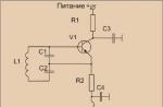
1 - fuel supply pipe (copper, Ø 3 mm), 2 - heat exchanger-evaporator, 3 - nozzle supply pipe (copper, Ø 3 mm), 4 - steam extraction pipe, 5 - water evaporator (tube Ø 3-4 mm) , 6 - blinds for supplying air to the flame, 7 - nozzle, 8 - nozzle mounting unit, 9 - lower chamber, 10 - water supply pipe to the evaporator, 11 - housing-pipe.
Heat exchanger - fuel evaporator can be made from a copper box from an old barometer or in the form of a coil of a thin copper tube. The fuel spray nozzle is converted from a toilet sprayer.

1 - steam supply pipe from the boiler to the engine, 2 - brass valve body, 3 - spring, 4 - ball valve. For the valve to work in the bottom of the engine piston, it is necessary to mount the pusher rod in the center, which, when the piston approaches the top dead center, must press the ball-valve up, thus letting in the next portion of steam under pressure.


1 - body (roofing iron or sheet brass), 2 - filler neck (closes hermetically), 3 - valve (nipple from a bicycle or motorcycle), 4 - consumable tap valve.
Preparation for testing a steam engine is not difficult. Machine oil is poured into the crankcase of the converted internal combustion engine; a plug is inserted into the standard carburetor diffuser (the oil must be changed after about 50 hours of machine operation). The tanks are filled with water (preferably distilled, which will prevent the formation of scale in the steam system) and gasoline of any brand, respectively. Both tanks are hermetically sealed. Then, an ignited tablet of dry alcohol is placed in the lower part of the steam boiler, and air is pumped into them through the nipples soldered into the tanks, creating excess pressure. Now you can open the consumable taps-valves. After some time, when the fuel evaporation heat exchanger warms up, the boiler's flame system will switch to automatic mode, constantly supplying gasoline under pressure to the nozzle nozzle. To make the engine work, it is enough to turn its crankshaft a couple of times. Motor speed is controlled by water supply and flame height.
It began its expansion at the beginning of the 19th century. And already at that time, not only large units for industrial purposes were being built, but also decorative ones. Most of their customers were rich nobles who wanted to amuse themselves and their kids. After steam engines were firmly established in the life of society, decorative engines began to be used in universities and schools as educational models.
Steam engines of today
At the beginning of the 20th century, the relevance of steam engines began to decline. One of the few companies that continued to produce decorative mini-engines was the British company Mamod, which allows you to purchase a sample of such equipment even today. But the cost of such steam engines easily exceeds two hundred pounds, which is not so little for a trinket for a couple of evenings. Moreover, for those who like to assemble all kinds of mechanisms on their own, it is much more interesting to create a simple steam engine with their own hands.
Very simple. The fire heats the cauldron of water. Under the action of temperature, the water turns into steam, which pushes the piston. As long as there is water in the tank, the flywheel connected to the piston will rotate. This is the standard layout of a steam engine. But you can assemble a model and a completely different configuration.
Well, let's move on from the theoretical part to more exciting things. If you are interested in doing something with your own hands, and you are surprised by such exotic machines, then this article is just for you, in it we will be happy to tell you about the various ways to assemble a steam engine with your own hands. At the same time, the very process of creating a mechanism gives joy no less than its launch.
Method 1: DIY mini steam engine
So, let's begin. Let's assemble the simplest steam engine with our own hands. Drawings, complex tools and special knowledge are not needed.
To begin with, we take from under any drink. Cut off the bottom third. Since as a result we get sharp edges, they must be bent inward with pliers. We do this carefully so as not to cut ourselves. Since most aluminum cans have a concave bottom, it needs to be leveled. It is enough to firmly press it with your finger to some hard surface.

At a distance of 1.5 cm from the upper edge of the resulting "glass" it is necessary to make two holes opposite each other. It is advisable to use a hole punch for this, since it is necessary that they turn out to be at least 3 mm in diameter. At the bottom of the jar we put a decorative candle. Now we take the usual table foil, wrinkle it, and then wrap our mini-burner on all sides.

Mini nozzles
Next, you need to take a piece of copper tube 15-20 cm long. It is important that it is hollow inside, as this will be our main mechanism for setting the structure in motion. The central part of the tube is wrapped around the pencil 2 or 3 times, so that a small spiral is obtained.
Now you need to place this element so that the curved place is placed directly above the candle wick. To do this, we give the tube the shape of the letter "M". At the same time, we display the sections that go down through the holes made in the bank. Thus, the copper tube is rigidly fixed above the wick, and its edges are a kind of nozzles. In order for the structure to rotate, it is necessary to bend the opposite ends of the "M-element" 90 degrees in different directions. The design of the steam engine is ready.
Engine starting

The jar is placed in a container with water. In this case, it is necessary that the edges of the tube are under its surface. If the nozzles are not long enough, then you can add a small weight to the bottom of the can. But be careful not to sink the entire engine.
Now you need to fill the tube with water. To do this, you can lower one edge into the water, and the second draw in air as if through a tube. We lower the jar into the water. We light the wick of the candle. After some time, the water in the spiral will turn into steam, which, under pressure, will fly out of opposite ends of the nozzles. The jar will begin to rotate in the container quickly enough. This is how we got a do-it-yourself steam engine. As you can see, everything is simple.
Steam engine model for adults

Now let's complicate the task. Let's assemble a more serious steam engine with our own hands. First you need to take a can of paint. You need to make sure that it is absolutely clean. On the wall, 2-3 cm from the bottom, we cut out a rectangle with dimensions of 15 x 5 cm. The long side is placed parallel to the bottom of the jar. From the metal mesh we cut out a piece with an area of 12 x 24 cm. From both ends of the long side we measure 6 cm. We bend these sections at an angle of 90 degrees. We get a small “platform table” with an area of 12 x 12 cm with legs of 6 cm. We install the resulting structure on the bottom of the can.
Several holes must be made around the perimeter of the lid and placed in a semicircle along one half of the lid. It is desirable that the holes have a diameter of about 1 cm. This is necessary in order to ensure proper ventilation of the interior. A steam engine will not work well if there is not enough air at the source of the fire.
main element
We make a spiral from a copper tube. You need about 6 meters of 1/4-inch (0.64 cm) soft copper tubing. We measure 30 cm from one end. Starting from this point, it is necessary to make five turns of a spiral with a diameter of 12 cm each. The rest of the pipe is bent into 15 rings with a diameter of 8 cm. Thus, 20 cm of free tube should remain at the other end.
Both leads are passed through the vent holes in the lid of the jar. If it turns out that the length of the straight section is not enough for this, then one turn of the spiral can be unbent. Coal is placed on a pre-installed platform. In this case, the spiral should be placed just above this site. Coal is carefully laid out between its turns. Now the bank can be closed. As a result, we got a firebox that will power the engine. The steam engine is almost done with his own hands. Left a little.
Water tank
Now you need to take another can of paint, but of a smaller size. A hole with a diameter of 1 cm is drilled in the center of its lid. Two more holes are made on the side of the jar - one almost at the bottom, the second - higher, at the lid itself.
They take two crusts, in the center of which a hole is made from the diameters of the copper tube. 25 cm of plastic pipe are inserted into one crust, 10 cm into the other, so that their edge barely peeks out of the corks. A crust with a long tube is inserted into the lower hole of a small jar, and a shorter tube into the upper hole. We place the smaller can on top of the large can of paint so that the hole at the bottom is on the opposite side of the ventilation passages of the large can.
Result
The result should be the following design. Water is poured into a small jar, which flows through a hole in the bottom into a copper tube. A fire is kindled under the spiral, which heats the copper container. Hot steam rises up the tube.
In order for the mechanism to be complete, it is necessary to attach a piston and a flywheel to the upper end of the copper tube. As a result, the thermal energy of combustion will be converted into mechanical forces of wheel rotation. There are a huge number of different schemes for creating such an external combustion engine, but in all of them two elements are always involved - fire and water.

In addition to this design, you can assemble a steam one, but this is material for a completely separate article.