This circuit was taken from Radiohobby magazine No. 3 for 1999 and is a step-up voltage converter built on the principle of a blocking oscillator. Generation is carried out due to positive feedback that controls the operation of the key transistor. In this case, short-term high-voltage pulses are generated on the secondary winding of the transformer. When the converter is turned on, the fluorescent lamp has a high resistance, the voltage on its electrodes increases to 500 volts, but as soon as the lamp warms up, the voltage drops to 50 - 70 volts. Therefore, it is extremely important not to turn on the converter without a load, since the voltage on it can rise to 1000 volts, which can damage the transformer.

The figure shows two circuits, the top one is for a p-n-p structure transistor, the bottom one is for an n-p-n transistor. Naturally, when the structure of the transistor changes, the polarity of capacitor C1 also changes.
The transformer is manufactured on W-shaped ferrite 7x7 with magnetic permeability NM2000. The secondary winding is wound first, according to the diagram it is connected to the LDS. It contains 240 turns wound with PEV-0.23 wire. After which the winding is well insulated and the collector winding is wound on top of it - this is 22 turns wound with PEV-0.56 wire and the base winding, which contains 6 turns wound with PEV-0.23 wire. Naturally, the diameters of the wires can vary within small limits. The core required for the transformer being manufactured can be obtained from an old rotary telephone, for example TA-68. Then you must first remove all the old windings from its frame. Also, an W-shaped core of a suitable cross-section of the magnetic circuit can be taken from a computer power supply. Important! A gap is required between the halves of the W-shaped core - a gasket made of non-magnetic material. A sheet of thin paper, one layer of electrical tape, etc. will do. This is necessary so that the core does not become magnetized, otherwise the converter will stop working after a short time.
For the circuit to operate correctly, it is necessary to adjust the current consumed by the converter. To do this, you need to know the power of the LDS used. Let's say its power is 20 watts. Then the current consumed by the converter should be 20W/12V=1.66A. This current is set by selecting the base resistor R1.
Transistor T1 must be placed on the radiator. The area of the radiator is selected in such a way that after an hour of work you can safely hold on to it. Instead of transistors KT837F and KT805BM, you can use KT818 and KT819, respectively.
The functionality of the converter is checked as follows. If immediately after turning on the converter the lamp lights up dimly, and after a split second flares up at full strength, then everything is working normally. If the lamp continues to work dimly, then it is necessary to select R1, or even change the transistor. The wires from the transformer to the lamp must be as thick and short as possible, otherwise the lamp will light poorly or not light at all.
And now some photos.


It is very easy and simple to make a converter from direct current 12 Volts to direct current 310 Volts, which will allow you to power any devices with a switching power supply, because At the input of such a block there is always a diode bridge, which turns an alternating voltage of 220 Volts into a constant voltage of 310 Volts. The best application is to turn on the lamps from the vehicle's on-board network, because Inside a CFL (compact fluorescent lamp) there is an electronic converter with just such a rectifier at the input and the light bulb will light in exactly the same way as from a 220V network. It can also be used to charge a cell phone, charge and operate a laptop, even a desktop computer can be powered through this converter, only a larger radiator for transistors is needed and a fan for it, a TV, DVD player, etc. equipment will work without problems.
But the most curious thing is that all the parts were taken from a dead computer power supply.
Here's the diagram:
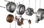
The transformer is taken ready-made from a computer power supply. It is easy to distinguish him from others there - he will have a “pigtail”. 5 Volt windings are used.
The microcircuit is also taken from the power supply - this is the master oscillator for PWM. All the details in its harness are taken from there. It is even preferable to take not the ratings from the circuit, but those ratings that worked with the donor transformer, then the efficiency of the converter will be the best (frequency and duty cycle will correspond to the parameters of the transformer).

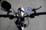
I assembled this converter on a breadboard and stuffed it into a spotlight designed for 30W CFL.

I connected a 5m long wire with crocodile clips at the end and plugged in the power switch.

The result is a camping lamp that shines no worse than a 500W halogen spotlight with a consumption of only 35W. The car one is enough for 10-15 hours of glow, i.e. for several evenings, away from electrical networks, there will be bright light for the camp and charging of any cell phones, navigators, radio stations, etc.
As a development of this device, it is necessary to build in protection against polarity reversal (otherwise there is a risk of failure of the converter) and protection against complete discharge of the battery. I’ll post the design of the simplest, like all ingenious, protection against battery discharge a little later.
The circuit allows you to power small fluorescent lamps (LDLs) up to 20 W from a car battery for up to 60 hours. The current consumed by the circuit is about 0.750A. This scheme is actually unique.
Device details
Assembled on a ferrite Ш-shaped core Ш8х8. When making a transformer, pay attention to the quality of the winding. The winding should be winding turn to turn, with each layer wrapped with either capacitor paper or fluoroplastic tape. After winding all the windings, the transformer must be impregnated with epoxy resin diluted in alcohol to prevent breakdown of the windings.
The winding data of the transformer is given below:
|
Winding |
Number of turns |
The wire |
|
PEV-2 0.5mm |
||
|
PEV-2 0.3mm |
||
|
III |
500 |
PEV-2 0.15mm |
The dots indicate the beginning of the windings. First, we wind the third winding, then we attach the terminal of the second winding to the terminal of the third winding and wind it in the opposite direction. Then, having carefully wrapped these two windings with varnished cloth, we wind the first winding.
The transistor must be placed on a radiator - an aluminum plate with an area of at least 20 cm2, which will serve as a heat sink. Before doing this, it is advisable to check for serviceability. Button 1 is used to ignite the lamp if this does not happen immediately, but usually the lamps light themselves.
After putting everything together, check the installation again. Did you make any mistakes in installation? If there are no errors, then connect the lamp and then apply power (Not vice versa! Otherwise, the transformer may break through!). If the lamp does not light up, then swap the terminals of winding I. Switch the ends of the winding - generation should occur. If it doesn't light up again, check the transistor.
Power supply for fluorescent lamps (LDS) from a 12 volt battery.
The converter allows you to power an LDS with a power of up to 20 W from a car battery with a glow duration of about 60 hours. The current consumption of the device is approximately 0.75 amperes. The schematic diagram of the converter is shown in the figure below.
Transformer TP1 is implemented on a ferrite Ш-shaped core Ш8х8. The wire is wound turn by turn, with each layer of wire wrapped in capacitor paper (thin fluoroplastic tape will do instead of paper). Pay special attention to the quality of winding of the transformer, wind it carefully, and at the end of the procedure, to avoid breakdown, impregnate it with epoxy resin (the resin is diluted with alcohol before impregnation).
Winding data of transformer TP1:
● I winding - 30 turns of PEV-2 wire with a diameter of 0.5 mm;
● II winding - 12 turns of PEV-2 wire with a diameter of 0.3 mm;
● III winding - 500 turns of PEV-2 wire with a diameter of 0.15 mm.
In the diagram, the dots indicate the beginning of each of the windings. Pay attention to the winding sequence:
● the third winding is wound first and wrapped with capacitor paper;
● the wire for the second winding is connected to the beginning of the first winding and it is wound in the opposite direction, then a layer of paper or fluoroplastic tape;
● the third winding is wound and then impregnated.
To avoid thermal breakdown of the transistor, it should be installed on a radiator, which can be made independently from sheet aluminum. The area of the radiator plate must be at least 20 cm2. For the parameters of the KT863 transistor, see the figure below.
Button SW1, which closes the circuit of capacitor C4, is necessary to start the LDS, but, as a rule, after power is applied to the converter, the LDS lights up immediately.
After assembling the converter, before turning it on, make sure again that there are no installation errors, connect the lamp and apply voltage to the device. The lamp should light up. If the lamp does not light up and the SW1 button does not help, check the serviceability of the transistor, if the transistor is working properly, swap the leads of the first winding, the generator should work.
Homemade neon lighting for the underbody of a car.
Fans of all kinds of “mulek”, “fenech”, and other automotive gadgets, along with the embellishment of the interior of their car, also get to the bottom of the body; they like it when, driving through the evening city, their bolivar glows like a New Year tree.
Of course, nowadays in stores you can buy all kinds of ready-made automotive gadgets, including underbody lighting, but sometimes not everyone is happy with the price. That’s why craftsmen have to put their hands to it to make such a “luminary” with their own hands.
Below we present to your attention a simple, repeated converter circuit capable of lighting fluorescent lamps with a power of 20 to 40 watts when powering the device from a 12-volt car battery.

It is worth noting that the purpose of this converter for LDS lamps is not limited to illuminating the underbody. It can be used as a backup lighting device when the main power supply is turned off (emergency lighting), or a portable low-voltage lamp can be made for use in all kinds of hikes (trips to the forest or fishing, outdoor recreation with an overnight stay, etc.). In general, the thing is useful, all that remains is to sculpt it, since the design of the device is quite primitive and parts for it are not in short supply. The only thing you need to pay attention to is the quality of winding of the transformer, which, unlike the previous version described above, is wound on a ferrite rod with a diameter of 8 mm and a length of about 5 - 8 cm.
And this is how to wind a transformer:
● We take a ferrite rod of the size we need, wrap a layer of thin, well-sticking (preferably imported) electrical tape around it;
● We wind the high-voltage winding III as follows: we take a coil of wire with a diameter of 0.2 - 0.3 mm and solder a piece of multicore to the end, which will serve as a tap, apply ferrite to one edge of the ferrite wrapped in a layer of electrical tape, and wind tightly turn to turn one layer of winding until filling the ferrite length. We apply one layer of electrical tape to this layer of winding. We continue to wind in the opposite direction along the entire length of the ferrite rod. We also cover the second layer of the winding with a layer of electrical tape. In this way we wind the entire high-voltage winding. For lamps from 8 to 16 watts, the winding contains 600...700 turns, for lamps from 20 to 40 watts - wind 100 turns more.
![]()
● It remains to wind the primary and secondary windings. They are wound alternately in one direction as shown in the diagram (the dots indicate the beginning of the windings), and do not forget to lay a layer of insulating tape between these windings. The permissible wire diameter for winding the primary and secondary windings is 0.5...1.2 mm (it is better to choose something in between). The primary winding contains 25 turns, the secondary winding contains 45 turns.
![]()
During the process of assembling the device, do not confuse which winding is which, this may result in the fact that your LDS will not burn (at best), or the converter transistor will “crack” (at worst).
What else can you say about the assembly...
Diode KD226 can be replaced with any other “current” (3 amperes) diode, with a voltage of at least 50 volts, or some imported one with similar parameters (for example FR607 - current 6A, 1000 volts). Below for reference, see the characteristics of KD226 and select the appropriate one if you do not have what is indicated in the diagram.
Resistors R1 and R2 It’s better to install not half-watt ones, as in the diagram, but one-watt ones, especially R2, because during operation they tend to heat up. By selecting these resistors, the required current consumption of the converter is set (0.6...0.8A), which determines how brightly the lamp will glow. There is no point in increasing the current consumption; the difference in brightness with a further increase in current will not be large, and the transistor will glow “Mother, don’t worry...”. If, when setting up, the current is already quite high, but the LDS still does not want to shine normally, it is better not to chase the consumption current, but try to increase or decrease the capacitance of capacitor C1, its capacitance can be adjusted within 0.05...0.5 µF.
Resistance R1 is selected depending on the power of the lamp that you plan to use; its nominal value can lie in the range of 430 Ohm ... 2 kOhm. For example, when using an 8-watt LDS, R1 will be about 2 kOhm, and when using a 30…40W LDS, it will be within 360…820 Ohms.
Transistor KT805AM installed on a radiator, possibly made of sheet aluminum, with a cooling area of about 100 cm2. It’s better to put the finished device into operation for an hour, and then check how hot the transistor is. Slightly warm - that means it’s normal, it will live. Yes, and the quality of the lamp’s glow depends on the transistor; with one LDS it may not light up reliably, but with the same one it lights up immediately, although both transistors are working. The table below shows the parameters of KT805 transistors. Can be replaced with KT819G.
How to check the functionality of the converter:
● Be sure to connect the lamp (do not supply power to the inverter without the lamp connected, and do not disconnect the lamp while the inverter is running);
● Apply power to the inverter. The LDS lights up dimly at first, but after a second it lights up brightly - everything means good.
● If your light lights up dimly, and there is a glow along one edge of the LDS, try increasing Ipot; if the current consumption is normal, change VT1 to another.
● Do not make the wires connecting the lamp to the converter too long, and do not use too thin a wire for these purposes; this determines how well the LDS will ignite, and whether it will ignite at all.
● And one more way to check the converter: carefully move the wires from the high-voltage winding to a gap of approximately 5 ... 10 mm. If a trailing spark jumps in this gap, then the device is working. If not, shorten the wires, the number of turns of the high-voltage winding is not enough, or change VT1.

Attention!!! Be careful when setting up the converter, there is a high voltage on the 3rd winding of the transformer when power is applied to the circuit; Observe electrical safety precautions.
Lamps for illuminating the underbody.
In general, such lamps are produced not only with a white glow, they also come in pink, blue, and green. T4 standard lamps with a power of 20 watts are quite enough for these purposes. For example, you can use F20W T4 BLUE, this lamp has a blue glow. Dimensions of this lamp: length – 57cm, diameter – 1cm.
Before attaching the lamp to the underbody, wires are connected to its contacts and it is placed in a transparent PVC tube. The length of the tube is chosen to be 8...10 centimeters longer than the lamp, so that it is possible to fill the ends of the tube with liquid nails, and use self-tapping screws to attach the lamp to the body or frame using the remaining free areas.

PS. It is better to select the part ratings (R1, R2, C1) for each specific lamp. If the converter is configured at home when operating from a power supply, ensure that the LDS is reliably ignited at a voltage of 11 volts. When set to Up = 13V, and then installing the device on the car, the lamps may glow poorly even when using wires with a cross-section of 0.75 mm.


COSTAS I don’t understand the diagrams, I want to assemble various ready-made parts from the designer.Ptramids are a separate conversation, I don’t want to convince you*
About the ozonator and the rest, I understood your skeptical attitude.
But I want to create an ozonator similar to Dudyshev’s, if you can help me with your electrical knowledge.
From practice, about the ozonizer, I can say that 7 years ago, having an uninterruptible power supply from my computer, I put this bactericidal lamp in the corrugation and connected it in front of the filter on OKE, saving 2 liters but only in the city due to traffic jams. On the highway, the evekt lost its clear why there was a lack of ozone concentration. The master who adjusted the CO and the carburetor, the poor thing suffered, but the stubborn one (Georgian or Armenian) even drilled out the ignition adjustment. And I put another screw in the caburator. But he could not understand why at xx the CO decreases to 1.5 tischi below the norm and then appears again above. And the Okushny two doors were repaired for 70 thousand, but I got 150 thousand, and maybe it would have been more, but I crashed the car.
After installing the lamp and adjustments, the oil from the oil was much lighter, I then checked it for quality, on swings in the yard, loops in the entrance, etc., in general, it did not lose its properties and stank less. I barely remember the mineral water, I remember that it was 80 rubles more expensive than the cheapest one, I changed it every 10 thousand. I never threw everything away during detention. While it was filtered through paper, the gasoline evaporated and did not smell like anything at all, it dripped into the barrel with the burnts, the burnts were soaked and the usual burnt on for the start and then 2 soaked for the whole night.* I was skeptical about the pyramid, ha ha some kind of figurine can do something.
But I wouldn’t be Vasya if I hadn’t checked. Let me note that I am a religious person.
Defended the pyramid with micron precision in Corel Drave 11.
There was a problem printing, the printers froze, it drove me crazy. What the hell is this all nonsense, why isn’t it printing? As a result, after 2 years, a modern HP plotter in A3 format printed a scan (that can then be folded), but it turns out that the 3rd side is different from the others. I check the file, there really are differences. I make a new scan based on one face, print it out, again it doesn’t converge and changes have occurred in the saved file. A copy of the file not printed on the plotter to the printing center is rejected after half an hour. He whispered at the entrance, and it turned out that the plotter died.
Slaveni And you think I would have stopped there, but it’s serious, I found out that everywhere where SP2 Pyramid does not print, it burns or freezes.
I dug out a 98 Windows disk and printed out the paper on an A3 cutting plotter for 150 grams, almost cutting it so that it folded exactly along the edges, folded it, which resulted in 2 years of torment. I glued it together and checked it.
If your legs are twisting before precipitation (weather), we put the pyramid under the bed and orient it and your legs don’t twist. Your beloved took part in the experiment, chaotically removing and installing the pyramid. As a result, he stands under the bed and forgot about it and his legs before the precipitation.
Experiment 2
Vest blades poppy 3 killed - sharpened within a year. paper pyramid 19 cm high
Experiment 3
I took the girl to the airport and saw her off. They stopped the X-ray scanner, 3 times the bag back and forth, she was at a loss. I apologized, explained myself, I looked to help, and then the whole monitor turned white when her bag went through, the cop pulled out all the metal and plastic, the bag went through, then the metal went through and then the plastic and again the X-ray went off scale. A plastic hollow pyramid from the Crimea appeared and scaled the X-ray. As a result, the primer took root in my car on the dashboard. The black one does not reflect, it works, it does not work, check there are no underground Nexias..
130 thousand for 3 years and I haven’t changed anything, just front brake discs and consumables
Fuck the pyramid, we need to build an ozonator!!! Based on ready-made parts, I connected it and it works...
PS: I froze, my enthusiasm kept me from falling asleep, and when I got home it crashed, sorry for the mistakes.