Designed for spraying fuel supplied to it under high pressure.
PRINCIPLE OF OPERATION
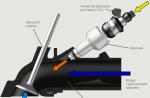
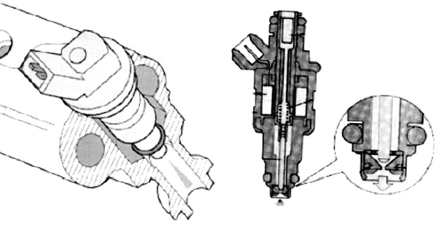
Rice. An example of the design of injectors for distributed (a) and central (mono) injection systems (b): 1 - fuel filter, 2 - sealing rings, 3 - locking element, 4 - seat, 5 - spring, 6 - winding, 7 - housing, 8 - electrical connector
The device of an electric nozzle may be different (examples of designs are shown in the figure), but the principle of operation is the same for all types of nozzles.
The nozzle is a certain form of a container with fuel. On the one hand, fuel under pressure enters from the fuel line through the filter mesh, and on the other hand, in the atomized state, it enters the working area of the ENGINE if voltage is applied to the injector solenoid valve.
- MONO injection- one nozzle (usually an in-line engine up to 4 cylinders)
- DOUBLE MONO injection- two nozzles working on two halves, usually a 6-cylinder, V-shaped engine
- DISTRIBUTION injection- one nozzle per cylinder, the working part is located in the intake manifold
- DIRECT injection- one nozzle per cylinder, the working part is located inside the cylinder
- LAUNCH- one for the engine, the working part is located in the intake manifold
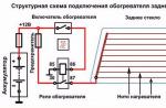
Atomizers are LOW-RESISTANCE (from 1 to 7 ohms) and HIGH-RESISTANCE (from 14 to 17 ohms). Low-resistance injectors are controlled by reduced voltage or there are additional resistances (5-8 Ohms) in the control circuits. A fragment of the circuit with additional resistances (152) is shown in the figure.
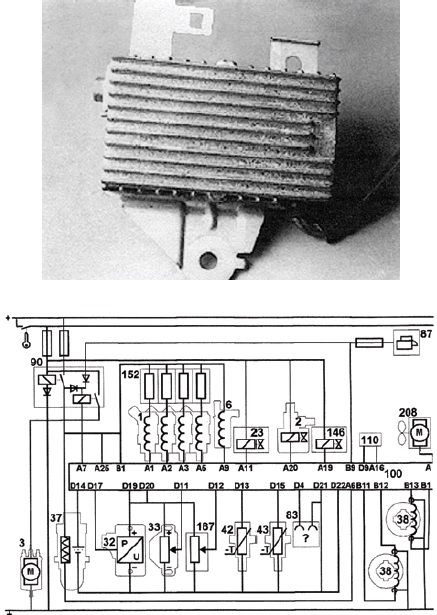
Rice. A fragment of the control system diagram and a photo of the resistance unit.
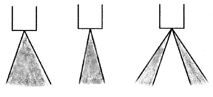
Rice. The shape of the atomized fuel jet is different.
The waveform showing the waveform of the injector, with port injection (PFI) and sequential injection (SFI) systems that use a turn off saturation transistor drive, is shown side by side and labeled A. The injector solenoids are turned on by the engine control unit. The voltage drops sharply when the valve is open and then rises sharply when the voltage is turned off (due to the inductance of the solenoid). The pulse width changes depending on the motor load.
An oscillogram showing the pulse shape of a single injection injector (TBI). Such systems use peak and synchronization current drivers to turn the injectors on and off. The injector solenoid valves are activated when there is a high supply current supplied from the engine control unit.
After actuation, the current decreases and keeps the valve open. There is a sudden voltage drop when the valve first opens and then a sudden voltage increase when the current driver generates less synchronizing current than the high turn-on current. When the solenoid turns off (after a synchronization period) a voltage amplitude is created due to the inductance of the solenoid coil (diagram B).
Some peak current and sync current drivers produce fast voltage switching during the sync period due to the low resistance of the injector solenoid coil (diagram C).
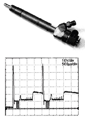
Rice. Distributed fuel injection nozzle.
An example is the oscillogram of the injector of the car FORD "Sierra" 1.6i, EEC 4 below.
Rice. Injector waveform
Below are the connection diagrams for injectors with simultaneous, group and phased fuel injection.
With the simultaneous and group method, all injectors connected in parallel inject fuel at the same time, and half of the full portion of fuel is injected in one revolution of the crankshaft.
This method of connecting nozzles was used on cars produced in the 80s - early 90s.
Modern engine control systems use sequential or phased fuel injection. This control method allows you to link the moment of injection with the moment of opening the intake valve in a particular cylinder, to change the amount of fuel supplied to the cylinder.
![]()
Rice. Injector connection diagrams for simultaneous, group and phased fuel injection
The following designations are used on the diagrams: 1,2,3,4 - injectors, 5 - engine ECU.
The injectors of direct fuel injection systems are different from the injectors used on intake manifold fuel injection systems. The nozzle atomizer is located directly in the combustion chamber and experiences high temperature and high pressure loads. The direct injection nozzle is longer because it is necessary to pass the thickness of the block head. The fuel pressure is much higher than in conventional injection systems and the spray pattern is different for each engine. These features of direct injection systems can be attributed to gasoline and diesel engines. The figure shows the injector and its oscillogram of the CITROEN HDI engine. The resistance of the solenoid winding of the nozzle is 0.3 - 1 ohm.
Rice. HDI direct injection injector and waveform taken in XX mode.
LOCATION
START nozzle usually located in the intake manifold so that its wide jet of atomized fuel (up to 90 degrees) falls into the region of the intake valves of all cylinders.
MONO injection nozzle is located in place of a conventional carburetor and fuel is injected into the total volume of the intake manifold.
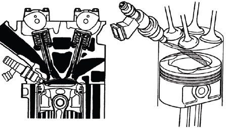
INJECTION INJECTORS located on the intake manifold near the intake valves of each cylinder. If there are two inlet valves, then the atomized fuel jet consists of two parts, each of which is directed under one of the valves.
DIRECT injection nozzles located in the block head. The atomizer is located in the cylinder and has a narrow slot that forms a torch directed at an angle to the piston bottom.
One of the fundamental differences between direct fuel injection systems is that, depending on the engine operating mode, the fuel pressure is regulated within 80-130 atm. The control system controls both the moment of injection, which occurs during the suction stroke, and the portion of fuel, changing the pressure in the pipeline and the duration of the nozzle opening.
FAULTS
The resistance of the injector winding must correspond to the reference data. Typically injectors have a fine mesh at the inlet, which can become clogged with small particles of impurities or rust from the tank and fuel lines.
If the inlet mesh does not retain impurities, then passing through the locking element and nozzle seat, these parts receive additional wear due to the abrasive properties of foreign particles. Gradually, the shape of the torch changes or disappears altogether and the nozzle pours fuel in a regular stream, which does not contribute to the correct operation of the engine.
Resin deposits gradually accumulate on the nozzle sprayer. Sometimes deposits form as a result of using a gas installation on an engine.
VERIFICATION METHOD
Checking the fuel part of the injector must be started by connecting to a stand-alone unit that can create a working pressure at the inlet to the injector. At the same time, no fuel should drip or flow from the nozzle. When the injector is briefly connected to a 12 V power supply (high-resistance injectors 14-17 ohms, low-resistance injectors - from 2 to 7 ohms through an additional resistance of 10-15 ohms), loud clicks of the shut-off valve drawn in by the magnetic field of the solenoid should be heard. If the nozzle "does not click", then everything inside is probably clogged with rust. Such a nozzle goes "on the last journey." If the initial checks give a positive result, we check the shape of the torch and the degree of atomization of the fuel, as well as the performance of the nozzle per unit time - this is usually 80 - 90 ml. in 30 seconds (50 - 60 ml. for small engines).