Click Class
Tell VK
Dear visitors, hello everyone!!!
In this topic, you will get acquainted with a car generator, using the example of a VAZ 2115, that is, with its device, principle of operation, with an electrical circuit and an explanation that will be given to the circuit.
In a conversation with our friends, each of us explained something different in the sense of how exactly a car generator should be called correctly - an alternating current generator or a direct current generator. If a car generator generates alternating current, then how will the current feed the consumers of the car? The question arises, how should the name of the generator be correctly attributed to a variable or a constant?
The correct answers to various questions concerning vehicles can be found in the relevant technical literature. Currently, alternators are widely used in cars. However, this can be understood from the very electrical circuit of the generator.
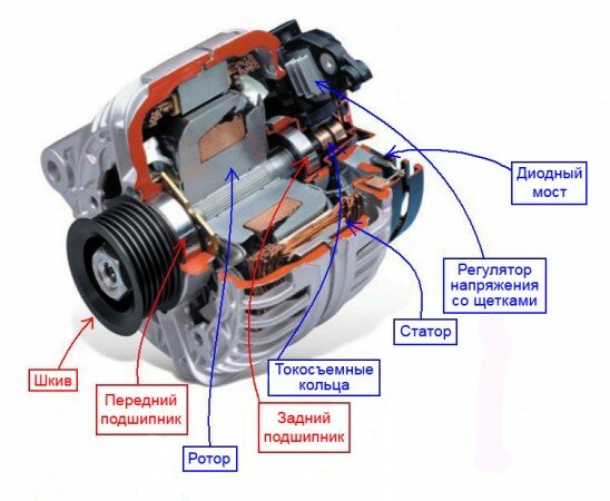
Automobile generator device
In this figure, the device of a car generator, everything is described in detail - what and where is located.
Let's take a look at the positions of what and how it works here. Let's start with the generator shaft. Pressed on the generator shaft:
- rotor shaft front bearing (15);
- rotor bushing (23);
- rotor pole pieces (21);
- bearing bush (26) together with rear rotor shaft bearing (25);
- insulating sleeves on which slip rings (27) are pressed.
On the rotor, between the sleeve (23) and the pole pieces of the rotor (21), on the sleeve itself, the excitation winding of the rotor (24) is wound. The two ends of the rotor excitation wire are connected to slip rings (isolated from each other). The voltage is removed from the slip rings by touching the brushes installed in the brush holder (28). One brush of the automobile alternator is connected to the alternator housing (ground), and the second brush is connected to the output Sh. Further explanation will be given on the electrical circuit of the generator.
The principle of operation of a car generator
The principle of operation of a car generator is simple - as for all electrical machines, as they are commonly called in general. Initially, when starting the car engine, the excitation winding of the generator is powered by battery 5 (Fig. 3) and later, during engine operation, this winding is powered by rectifier 2 (Fig. 3). Here the question arises: Why is the excitation winding (see Fig. 3) during the operation of the motor receives power from the rectifier (2)?
The drive of automobile generators is carried out from the crankshaft of the engine, by means of a belt drive. When the rotor rotates, the magnetic field lines of the excitation winding cross the stator winding, thereby, an electromotive force is induced in the stator winding - EMF. Thus, at the ends of the stator windings, an alternating voltage is initially generated, which is subsequently converted to a constant voltage, due to the block of silicon diodes of the rectifier (position 2, Fig. 3) and, accordingly, it turns out that the rotor excitation winding (when the car engine is running) is powered from the rectifier.
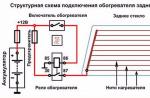
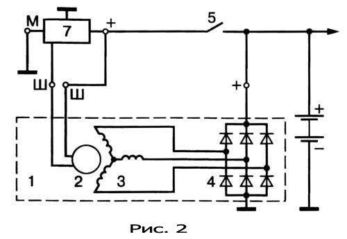
Automotive alternator circuit
Consider the positions (Fig. 2), what the scheme consists of:
- alternator;
- rotor;
- stator windings connected according to the "star" scheme;
- block of rectifier diodes;
- ignition switch;
7. voltage regulator;
As you noticed, the sixth position is missing in the diagram - this is the battery. I took this scheme of a car generator from the Internet, with which I do not fully agree with respect to positions (2) and (7). If I further explain what I disagree with, it will look like an incorrect explanation.
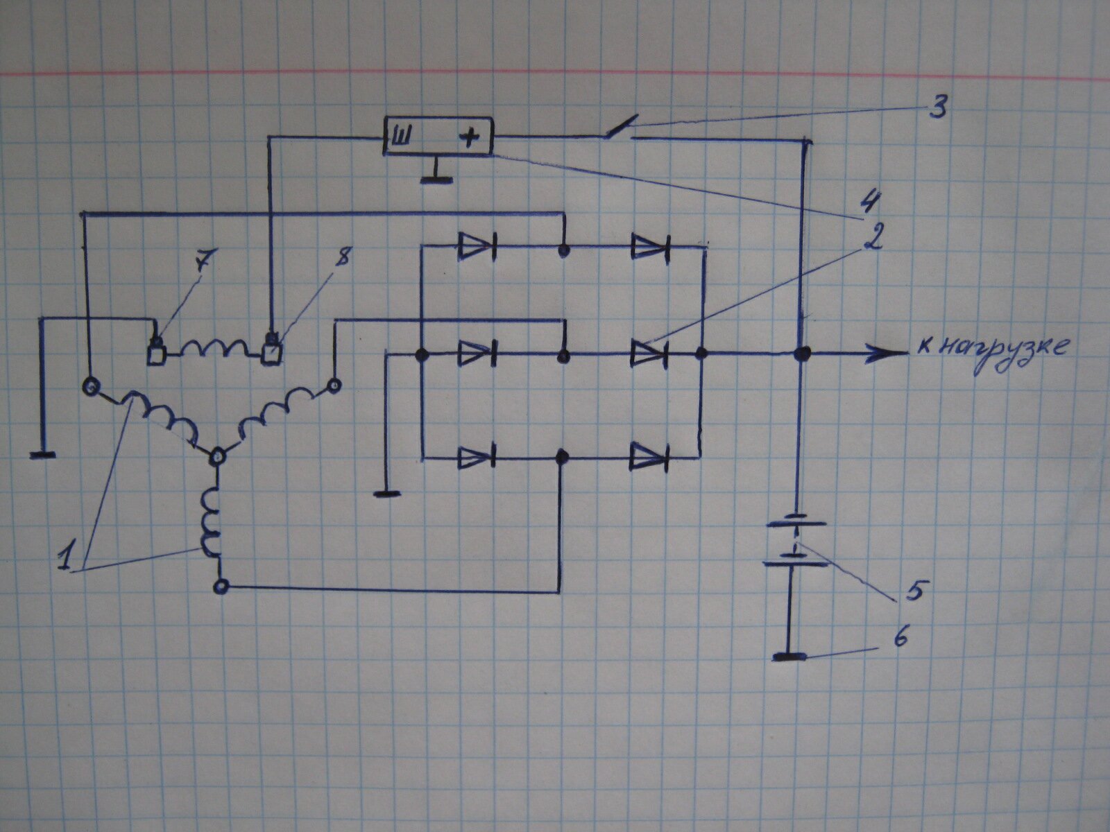
Let's consider another diagram from my outlined notes, according to which a more objective explanation can be given. So, in the diagram (Fig. 3) of an automobile alternator, the following numbered positions are placed:
1-stator winding;
2-block silicon diode rectifier;
3-ignition switch;
4-voltage regulator;
5-battery;
8 pin rings.
The excitation winding of the rotor is located between the slip rings, that is, the ends of the winding are soldered to the slip rings. One end of the contact winding (7) is connected to the vehicle ground, the other end of the excitation winding (8) is connected to the voltage regulator (4).
And here are two contacts with the designation Ш, which are indicated in the diagram in Fig. 2? This is exactly what I don't agree with. How to explain where the excitation winding of the rotor is here? How to explain what the rotor winding is connected to according to this scheme?
Let's continue the explanation of the scheme (Fig. 3). The generator, as we see from the diagram, has three outputs. The output Ш from the brush (8) is connected to the output Ш of the voltage regulator (4), the body of the voltage regulator is connected to the ground. The wire from the anode group of the rectifier (2) with negative polarity is connected to ground. The wire from the cathode group with a positive polarity of the same rectifier is connected to the load, then through a branch, to the battery and the ignition switch.
Each separate phase from the ends of the stator windings, the windings of which are connected by a "star", are attached to a block of silicon diodes of the rectifier, where each phase is connected between two diodes with different polarity.
According to the scheme of an automobile alternator and its principle of operation, in general, everything should be clear. The explanation for this scheme is given on the basis of the read technical literature and outlined materials. To describe in more detail the content, for example, of the principle of operation of the rectifier unit - this will turn out to be generally not a topic, but something else.