Somehow recently I came across a circuit on the Internet for a very simple power supply with the ability to adjust the voltage. The voltage could be adjusted from 1 Volt to 36 Volt, depending on the output voltage on the secondary winding of the transformer.
Take a close look at the LM317T in the circuit itself! The third leg (3) of the microcircuit is connected to capacitor C1, that is, the third leg is INPUT, and the second leg (2) is connected to capacitor C2 and a 200 Ohm resistor and is an OUTPUT.
Using a transformer, from a mains voltage of 220 Volts we get 25 Volts, no more. Less is possible, no more. Then we straighten the whole thing with a diode bridge and smooth out the ripples using capacitor C1. All this is described in detail in the article on how to obtain constant voltage from alternating voltage. And here is our most important trump card in the power supply - this is a highly stable voltage regulator chip LM317T. At the time of writing, the price of this chip was around 14 rubles. Even cheaper than a loaf of white bread.
Description of the chip
LM317T is a voltage regulator. If the transformer produces up to 27-28 volts on the secondary winding, then we can easily regulate the voltage from 1.2 to 37 volts, but I would not raise the bar to more than 25 volts at the transformer output.
The microcircuit can be executed in the TO-220 package:

or in D2 Pack housing

It can pass a maximum current of 1.5 Amps, which is enough to power your electronic gadgets without voltage drop. That is, we can output a voltage of 36 Volts with a current load of up to 1.5 Amps, and at the same time our microcircuit will still output 36 Volts - this, of course, is ideal. In reality, fractions of volts will drop, which is not very critical. With a large current in the load, it is more advisable to install this microcircuit on a radiator.
In order to assemble the circuit, we also need a variable resistor of 6.8 Kilo-Ohms, or even 10 Kilo-Ohms, as well as a constant resistor of 200 Ohms, preferably from 1 Watt. Well, we put a 100 µF capacitor at the output. Absolutely simple scheme!
Assembly in hardware
Previously, I had a very bad power supply with transistors. I thought, why not remake it? Here is the result ;-)
Here we see the imported GBU606 diode bridge. It is designed for a current of up to 6 Amps, which is more than enough for our power supply, since it will deliver a maximum of 1.5 Amps to the load. I installed the LM on the radiator using KPT-8 paste to improve heat transfer. Well, everything else, I think, is familiar to you.
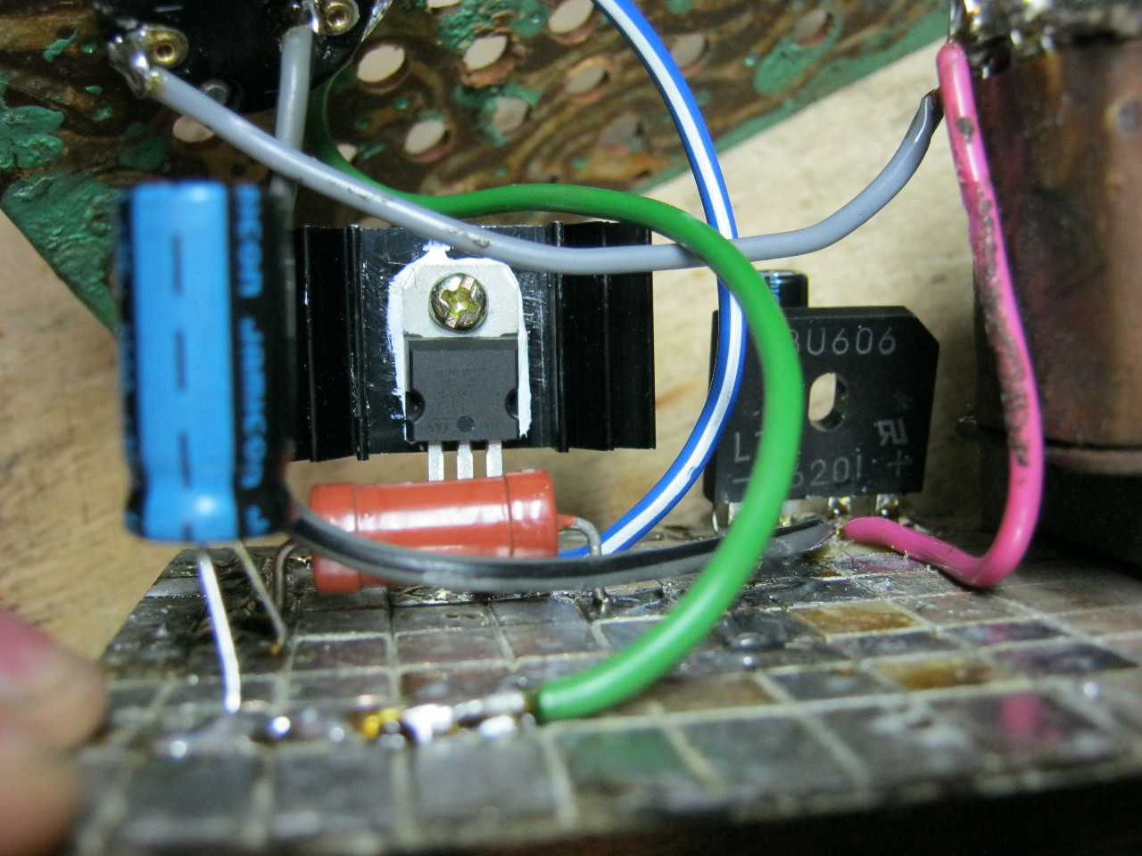
And here is an antediluvian transformer that gives me a voltage of 12 volts on the secondary winding.

We carefully pack all this into the case and remove the wires.

So what do you think? ;-)

The minimum voltage I got was 1.25 Volts, and the maximum was 15 Volts.


I set any voltage, in this case the most common are 12 Volts and 5 Volts


Everything works great!
This power supply is very convenient for adjusting the speed of a mini drill, which is used for drilling circuit boards.

Analogues on Aliexpress
By the way, on Ali you can immediately find a ready-made set of this block without a transformer.

Too lazy to collect? You can buy a ready-made 5 Amp for less than $2:

You can view it at this link.
If 5 Amps is not enough, then you can look at 8 Amps. It will be enough for even the most seasoned electronics engineer:

Lithium-Ion (Li-Io), charge voltage of one can: 4.2 - 4.25V. Further by the number of cells: 4.2, 8.4, 12.6, 16.8.... Charge current: for ordinary batteries is equal to 0.5 of the capacity in amperes or less. High-current ones can be safely charged with a current equal to the capacity in amperes (high-current 2800 mAh, charge 2.8 A or less).
Lithium polymer (Li-Po), charge voltage per can: 4.2V. Further by the number of cells: 4.2, 8.4, 12.6, 16.8.... Charge current: for ordinary batteries is equal to the capacity in amperes (battery 3300 mAh, charge 3.3 A or less).
Nickel-metal hydride (NiMH), charge voltage per can: 1.4 - 1.5V. Further by the number of cells: 2.8, 4.2, 5.6, 7, 8.4, 9.8, 11.2, 12.6... Charge current: 0.1-0.3 capacity in amperes (battery 2700 mAh, charge 0.27 A or less). Charging takes no more than 15-16 hours.
Lead-acid (Lead Acid), charge voltage per can: 2.3V. Further by number of cells: 4.6, 6.9, 9.2, 11.5, 13.8 (automotive). Charge current: 0.1-0.3 capacity in amperes (battery 80 Ah, charge 16A or less).
Many already know that I have a weakness for all kinds of power supplies, but here is a two-in-one review. This time there will be a review of a radio constructor that allows you to assemble the basis for a laboratory power supply and a variant of its real implementation.
I warn you, there will be a lot of photos and text, so stock up on coffee :)
First, I’ll explain a little what it is and why.
Almost all radio amateurs use such a thing as a laboratory power supply in their work. Whether it's complex with software control or completely simple on the LM317, it still does almost the same thing, powers different loads while working with them.
Laboratory power supplies are divided into three main types.
With pulse stabilization.
With linear stabilization
Hybrid.
The first ones include a switching controlled power supply, or simply a switching power supply with a step-down PWM converter. I have already reviewed several options for these power supplies. , .
Advantages - high power with small dimensions, excellent efficiency.
Disadvantages - RF ripple, presence of capacious capacitors at the output
The latter do not have any PWM converters on board; all regulation is carried out in a linear manner, where excess energy is simply dissipated on the control element.
Pros - Almost complete absence of ripple, no need for output capacitors (almost).
Cons - efficiency, weight, size.
The third is a combination of either the first type with the second, then the linear stabilizer is powered by a slave buck PWM converter (the voltage at the output of the PWM converter is always maintained at a level slightly higher than the output, the rest is regulated by a transistor operating in linear mode.
Or it is a linear power supply, but the transformer has several windings that switch as needed, thereby reducing losses on the control element.
This scheme has only one drawback, complexity, which is higher than that of the first two options.
Today we will talk about the second type of power supply, with a regulating element operating in linear mode. But let's look at this power supply using the example of a designer, it seems to me that this should be even more interesting. After all, in my opinion, this is a good start for a novice radio amateur to assemble one of the main devices.
Well, or as they say, the right power supply must be heavy :)
This review is more aimed at beginners; experienced comrades are unlikely to find anything useful in it.
For review, I ordered a construction kit that allows you to assemble the main part of a laboratory power supply.
The main characteristics are as follows (from those declared by the store):
Input voltage - 24 Volts AC
Output voltage adjustable - 0-30 Volts DC.
Output current adjustable - 2mA - 3A
Output voltage ripple - 0.01%
The dimensions of the printed board are 80x80mm.
A little about packaging.
The designer arrived in a regular plastic bag, wrapped in soft material.
Inside, in an antistatic zip-lock bag, were all the necessary components, including the circuit board. 
Everything inside was a mess, but nothing was damaged; the printed circuit board partially protected the radio components. 
I won’t list everything that is included in the kit, it’s easier to do this later during the review, I’ll just say that I had enough of everything, even some left over. 
A little about the printed circuit board.
The quality is excellent, the circuit is not included in the kit, but all the ratings are marked on the board.
The board is double-sided, covered with a protective mask. 
The board coating, tinning, and the quality of the PCB itself is excellent.
I was only able to tear off a patch from the seal in one place, and that was after I tried to solder a non-original part (why, we will find out later).
In my opinion, this is the best thing for a beginner radio amateur; it will be difficult to spoil it. 
Before installation, I drew a diagram of this power supply. 
The scheme is quite thoughtful, although not without its shortcomings, but I’ll tell you about them in the process.
Several main nodes are visible in the diagram; I separated them by color.
Green - voltage regulation and stabilization unit
Red - current regulation and stabilization unit
Purple - indicating unit for switching to current stabilization mode
Blue - reference voltage source.
Separately there are:
1. Input diode bridge and filter capacitor
2. Power control unit on transistors VT1 and VT2.
3. Protection on transistor VT3, turning off the output until the power supply to the operational amplifiers is normal
4. Fan power stabilizer, built on a 7824 chip.
5. R16, R19, C6, C7, VD3, VD4, VD5, unit for forming the negative pole of the power supply of operational amplifiers. Due to the presence of this unit, the power supply will not operate simply on direct current; it is the alternating current input from the transformer that is required.
6. C9 output capacitor, VD9, output protective diode. 
First, I will describe the advantages and disadvantages of the circuit solution.
Pros -
It's nice to have a stabilizer to power the fan, but the fan needs 24 Volts.
I am very pleased with the presence of a power source of negative polarity; this greatly improves the operation of the power supply at currents and voltages close to zero.
Due to the presence of a source of negative polarity, protection was introduced into the circuit; as long as there is no voltage, the power supply output will be turned off.
The power supply contains a reference voltage source of 5.1 Volts, this made it possible not only to correctly regulate the output voltage and current (with this circuit, voltage and current are regulated from zero to maximum linearly, without “humps” and “dips” at extreme values), but also makes it possible to control external power supply, I simply change the control voltage.
The output capacitor has a very small capacitance, which allows you to safely test the LEDs; there will be no current surge until the output capacitor is discharged and the PSU enters current stabilization mode.
The output diode is necessary to protect the power supply from supplying reverse polarity voltage to its output. True, the diode is too weak, it is better to replace it with another one.
Minuses.
The current-measuring shunt has too high a resistance, because of this, when operating with a load current of 3 Amps, about 4.5 Watts of heat are generated on it. The resistor is designed for 5 Watts, but the heating is very high.
The input diode bridge is made up of 3 Ampere diodes. It is good to have diodes with a capacity of at least 5 Amperes, since the current through the diodes in such a circuit is equal to 1.4 of the output, so in operation the current through them can be 4.2 Amperes, and the diodes themselves are designed for 3 Amperes. The only thing that makes the situation easier is that the pairs of diodes in the bridge work alternately, but this is still not entirely correct.
The big minus is that the Chinese engineers, when selecting operational amplifiers, chose an op-amp with a maximum voltage of 36 Volts, but did not think that the circuit had a negative voltage source and the input voltage in this version was limited to 31 Volts (36-5 = 31 ). With an input of 24 Volts AC, DC will be about 32-33 Volts.
Those. The op amps will operate in extreme mode (36 is the maximum, standard 30).
I'll talk more about the pros and cons, as well as about modernization later, but now I'll move on to the actual assembly.
First, let's lay out everything that is included in the kit. This will make assembly easier, and it will simply be clearer to see what has already been installed and what remains. 
I recommend starting the assembly with the lowest elements, since if you install the high ones first, then it will be inconvenient to install the low ones later.
It is also better to start by installing those components that are more of the same.
I'll start with resistors, and these will be 10 kOhm resistors.
The resistors are high quality and have an accuracy of 1%.
A few words about resistors. Resistors are color coded. Many may find this inconvenient. In fact, this is better than alphanumeric markings, since the markings are visible in any position of the resistor.
Don’t be afraid of color coding; at the initial stage you can use it, and over time you will be able to identify it without it.
To understand and conveniently work with such components, you just need to remember two things that will be useful to a novice radio amateur in life.
1. Ten basic marking colors
2. Series values, they are not very useful when working with precision resistors of the E48 and E96 series, but such resistors are much less common.
Any radio amateur with experience will list them simply from memory.
1, 1.1, 1.2, 1.3, 1.5, 1.6, 1.8, 2, 2.2, 2.4, 2.7, 3, 3.3, 3.6, 3.9, 4.3, 4.7, 5.1, 5.6, 6.2, 6.8, 7.5, 8.2, 9.1.
All other denominations are multiplied by 10, 100, etc. For example 22k, 360k, 39Ohm.
What does this information provide?
And it gives that if the resistor is of the E24 series, then, for example, a combination of colors -
Blue + green + yellow is impossible in it.
Blue - 6
Green - 5
Yellow - x10000
those. According to calculations, it comes out to 650k, but there is no such value in the E24 series, there is either 620 or 680, which means either the color was recognized incorrectly, or the color has been changed, or the resistor is not in the E24 series, but the latter is rare.
Okay, enough theory, let's move on.
Before installation, I shape the resistor leads, usually using tweezers, but some people use a small homemade device for this.
We are not in a hurry to throw away the cuttings of the leads; sometimes they can be useful for jumpers. 
Having established the main quantity, I reached single resistors.
It may be more difficult here; you will have to deal with denominations more often. 
I don’t solder the components right away, but simply bite them and bend the leads, and I bite them first and then bend them.
This is done very easily, the board is held in your left hand (if you are right-handed), and the component being installed is pressed at the same time.
We have side cutters in our right hand, we bite off the leads (sometimes even several components at once), and immediately bend the leads with the side edge of the side cutters.
This is all done very quickly, after a while it is already automatic. 
Now we’ve reached the last small resistor, the value of the required one and what’s left are the same, which is not bad :) 
Having installed the resistors, we move on to diodes and zener diodes.
There are four small diodes here, these are the popular 4148, two zener diodes of 5.1 Volts each, so it’s very difficult to get confused.
We also use it to form conclusions. 
On the board, the cathode is indicated by a stripe, just like on diodes and zener diodes. 
Although the board has a protective mask, I still recommend bending the leads so that they do not fall on adjacent tracks; in the photo, the diode lead is bent away from the track. 
The zener diodes on the board are also marked as 5V1. 
There are not very many ceramic capacitors in the circuit, but their markings can confuse a novice radio amateur. By the way, it also obeys the E24 series.
The first two digits are the nominal value in picofarads.
The third digit is the number of zeros that must be added to the denomination
Those. for example 331 = 330pF
101 - 100pF
104 - 100000pF or 100nF or 0.1uF
224 - 220000pF or 220nF or 0.22uF 
The main number of passive elements has been installed. 
After that, we move on to installing operational amplifiers.
I would probably recommend buying sockets for them, but I soldered them as is.
On the board, as well as on the chip itself, the first pin is marked.
The remaining conclusions are counted counterclockwise.
The photo shows the place for the operational amplifier and how it should be installed. 
For microcircuits, I do not bend all the pins, but only a couple, usually these are the outer pins diagonally.
Well, it’s better to bite them so that they stick out about 1mm above the board. 
That's it, now you can move on to soldering.
I use a very ordinary soldering iron with temperature control, but a regular soldering iron with a power of about 25-30 watts is quite sufficient.
Solder 1mm in diameter with flux. I specifically do not indicate the brand of solder, since the solder on the coil is not original (original coils weigh 1 kg), and few people will be familiar with its name. 
As I wrote above, the board is of high quality, soldered very easily, I did not use any fluxes, only what is in the solder is enough, you just need to remember to sometimes shake off the excess flux from the tip. 

Here I took a photo with an example of good soldering and not so good one.
A good solder should look like a small droplet enveloping the terminal.
But there are a couple of places in the photo where there is clearly not enough solder. This will happen on a double-sided board with metallization (where the solder also flows into the hole), but this cannot be done on a single-sided board; over time, such soldering may “fall off”. 
The terminals of the transistors also need to be pre-formed; this must be done in such a way that the terminal does not become deformed near the base of the case (elders will remember the legendary KT315, whose terminals loved to break off).
I shape powerful components a little differently. Molding is done so that the component stands above the board, in which case less heat will transfer to the board and will not destroy it. 
This is what molded powerful resistors look like on a board.
All components were soldered only from below, the solder that you see on the top of the board penetrated through the hole due to capillary effect. It is advisable to solder so that the solder penetrates a little to the top, this will increase the reliability of the soldering, and in the case of heavy components, their better stability. 
If before this I molded the terminals of the components using tweezers, then for the diodes you will already need small pliers with narrow jaws.
The conclusions are formed in approximately the same way as for resistors. 
But there are differences during installation.
If for components with thin leads installation occurs first, then biting occurs, then for diodes the opposite is true. You simply won’t bend such a lead after biting it, so first we bend the lead, then bite off the excess. 
The power unit is assembled using two transistors connected according to a Darlington circuit.
One of the transistors is installed on a small radiator, preferably through thermal paste.
The kit included four M3 screws, one goes here. 
A couple of photos of the nearly soldered board. I won’t describe the installation of the terminal blocks and other components; it’s intuitive and can be seen from the photograph.
By the way, about the terminal blocks, the board has terminal blocks for connecting the input, output, and fan power. 

I haven't washed the board yet, although I often do it at this stage.
This is due to the fact that there will still be a small part to finalize. 
After the main assembly stage we are left with the following components.
Powerful transistor
Two variable resistors
Two connectors for board installation
Two connectors with wires, by the way the wires are very soft, but of small cross-section.
Three screws. 
Initially, the manufacturer intended to place variable resistors on the board itself, but they are placed so inconveniently that I didn’t even bother to solder them and showed them just as an example.
They are very close and it will be extremely inconvenient to adjust, although it is possible. 
But thank you for not forgetting to include the wires with connectors, it’s much more convenient.
In this form, the resistors can be placed on the front panel of the device, and the board can be installed in a convenient place.
At the same time, I soldered a powerful transistor. This is an ordinary bipolar transistor, but it has a maximum power dissipation of up to 100 Watts (naturally, when installed on a radiator).
There are three screws left, I don’t even understand where to use them, if in the corners of the board, then four are needed, if you are attaching a powerful transistor, then they are short, in general it’s a mystery. 
The board can be powered from any transformer with an output voltage of up to 22 Volts (the specifications state 24, but I explained above why such a voltage cannot be used).
I decided to use a transformer that had been lying around for a long time for the Romantic amplifier. Why for, and not from, and because it hasn’t stood anywhere yet :)
This transformer has two output power windings of 21 Volts, two auxiliary windings of 16 Volts and a shield winding.
The voltage is indicated for the input 220, but since we now already have a standard of 230, the output voltages will be slightly higher.
The calculated power of the transformer is about 100 watts.
I parallelized the output power windings to get more current. Of course, it was possible to use a rectification circuit with two diodes, but it would not work better, so I left it as is. 
For those who don’t know how to determine the power of a transformer, I made a short video.
First trial run. I installed a small heatsink on the transistor, but even in this form there was quite a lot of heating, since the power supply is linear.
Adjustment of current and voltage occurs without problems, everything worked right away, so I can already fully recommend this designer.
The first photo is voltage stabilization, the second is current. 
First, I checked what the transformer outputs after rectification, as this determines the maximum output voltage.
I got about 25 Volts, not a lot. The capacity of the filter capacitor is 3300 μF, I would advise increasing it, but even in this form the device is quite functional. 
Since for further testing it was necessary to use a normal radiator, I moved on to assembling the entire future structure, since the installation of the radiator depended on the intended design.
I decided to use the Igloo7200 radiator I had lying around. According to the manufacturer, such a radiator is capable of dissipating up to 90 watts of heat. 
The device will use a Z2A housing based on a Polish-made idea, the price will be about $3. 
Initially, I wanted to move away from the case that my readers are tired of, in which I collect all sorts of electronic things.
To do this, I chose a slightly smaller case and bought a fan with a mesh for it, but I couldn’t fit all the stuffing into it, so I purchased a second case and, accordingly, a second fan.
In both cases I bought Sunon fans, I really like the products of this company, and in both cases I bought 24 Volt fans. 
This is how I planned to install the radiator, board and transformer. There is even a little room left for the filling to expand.
There was no way to get the fan inside, so it was decided to place it outside. 
We mark the mounting holes, cut the threads, and screw them for fitting. 
Since the selected case has an internal height of 80mm, and the board also has this size, I secured the radiator so that the board is symmetrical with respect to the radiator. 
The leads of the powerful transistor also need to be slightly molded so that they do not become deformed when the transistor is pressed against the radiator. 
A small digression.
For some reason, the manufacturer thought of a place to install a rather small radiator, because of this, when installing a normal one, it turns out that the fan power stabilizer and the connector for connecting it get in the way.
I had to unsolder them, and seal the place where they were with tape so that there would be no connection to the radiator, since there is voltage on it. 
I cut off the excess tape on the back side, otherwise it would turn out completely sloppy, we’ll do it according to Feng Shui :) 
This is what a printed circuit board looks like with the heatsink finally installed, the transistor is installed using thermal paste, and it is better to use good thermal paste, since the transistor dissipates power comparable to a powerful processor, i.e. about 90 watts.
At the same time, I immediately made a hole for installing the fan speed controller board, which in the end still had to be re-drilled :) 
To set zero, I unscrewed both knobs to the extreme left position, turned off the load and set the output to zero. Now the output voltage will be regulated from zero. 
Next are some tests.
I checked the accuracy of maintaining the output voltage.
Idling, voltage 10.00 Volts
1. Load current 1 Ampere, voltage 10.00 Volts
2. Load current 2 Amps, voltage 9.99 Volts
3. Load current 3 Amperes, voltage 9.98 Volts.
4. Load current 3.97 Amperes, voltage 9.97 Volts.
The characteristics are quite good, if desired, they can be improved a little more by changing the connection point of the voltage feedback resistors, but as for me, it’s enough as is. 
I also checked the ripple level, the test took place at a current of 3 Amps and an output voltage of 10 Volts 
The ripple level was about 15mV, which is very good, but I thought that in fact the ripples shown in the screenshot were more likely to come from the electronic load than from the power supply itself. 
After that, I started assembling the device itself as a whole.
I started by installing the radiator with the power supply board.
To do this, I marked the installation location of the fan and the power connector.
The hole was marked not quite round, with small “cuts” at the top and bottom, they are needed to increase the strength of the back panel after cutting the hole.
The biggest difficulty is usually holes of complex shape, for example, for a power connector. 
A big hole is cut out of a big pile of small ones :)
A drill + a 1mm drill bit sometimes works wonders.
We drill holes, lots of holes. It may seem long and tedious. No, on the contrary, it is very fast, completely drilling a panel takes about 3 minutes. 
After that, I usually set the drill a little larger, for example 1.2-1.3mm, and go through it like a cutter, I get a cut like this: 
After this, we take a small knife in our hands and clean out the resulting holes, at the same time we trim the plastic a little if the hole is a little smaller. The plastic is quite soft, making it comfortable to work with. 
The last stage of preparation is to drill the mounting holes; we can say that the main work on the back panel is finished. 
We install the radiator with the board and the fan, try on the resulting result, and if necessary, “finish it with a file.” 
Almost at the very beginning I mentioned revision.
I'll work on it a little.
To begin with, I decided to replace the original diodes in the input diode bridge with Schottky diodes; for this I bought four 31DQ06 pieces. and then I repeated the mistake of the board developers, by inertia buying diodes for the same current, but it was necessary for a higher one. But still, the heating of the diodes will be less, since the drop on Schottky diodes is less than on conventional ones.
Secondly, I decided to replace the shunt. I was not satisfied not only with the fact that it heats up like an iron, but also with the fact that it drops about 1.5 Volts, which can be used (in the sense of a load). To do this, I took two domestic 0.27 Ohm 1% resistors (this will also improve stability). Why the developers didn’t do this is unclear; the price of the solution is absolutely the same as in the version with a native 0.47 Ohm resistor.
Well, rather as an addition, I decided to replace the original 3300 µF filter capacitor with a higher quality and capacious Capxon 10000 µF... 
This is what the resulting design looks like with replaced components and an installed fan thermal control board.
It turned out a little collective farm, and besides, I accidentally tore off one spot on the board when installing powerful resistors. In general, it was possible to safely use less powerful resistors, for example one 2-Watt resistor, I just didn’t have one in stock. 
A few components were also added to the bottom.
A 3.9k resistor, parallel to the outermost contacts of the connector for connecting a current control resistor. It is needed to reduce the regulation voltage since the voltage on the shunt is now different.
A pair of 0.22 µF capacitors, one in parallel with the output from the current control resistor, to reduce interference, the second is simply at the output of the power supply, it is not particularly needed, I just accidentally took out a pair at once and decided to use both. 
The entire power section is connected, and a board with a diode bridge and a capacitor for powering the voltage indicator is installed on the transformer.
By and large, this board is optional in the current version, but I couldn’t raise my hand to power the indicator from the maximum 30 Volts for it and I decided to use an additional 16 Volt winding. 
The following components were used to organize the front panel:
Load connection terminals
Pair of metal handles
Power switch
Red filter, declared as a filter for KM35 housings
To indicate current and voltage, I decided to use the board I had left over after writing one of the reviews. But I was not satisfied with the small indicators and therefore larger ones with a digit height of 14mm were purchased, and a printed circuit board was made for them.
In general, this solution is temporary, but I wanted to do it carefully even temporarily. 
Several stages of preparing the front panel.
1. Draw a full-size layout of the front panel (I use the usual Sprint Layout). The advantage of using identical housings is that preparing a new panel is very simple, since the required dimensions are already known.
We attach the printout to the front panel and drill marking holes with a diameter of 1 mm in the corners of the square/rectangular holes. Use the same drill to drill the centers of the remaining holes.
2. Using the resulting holes, we mark the cutting locations. We change the tool to a thin disk cutter.
3. We cut straight lines, clearly in size at the front, a little larger at the back, so that the cut is as complete as possible.
4. Break out the cut pieces of plastic. I usually don't throw them away because they can still be useful. 
In the same way as preparing the back panel, we process the resulting holes using a knife.
I recommend drilling large-diameter holes; it does not “bite” the plastic. 
We try on what we got and, if necessary, modify it using a needle file.
I had to slightly widen the hole for the switch. 
As I wrote above, for the display I decided to use the board left over from one of the previous reviews. In general, this is a very bad solution, but for a temporary option it is more than suitable, I will explain why later.
We unsolder the indicators and connectors from the board, call the old indicators and the new ones.
I wrote out the pinout of both indicators so as not to get confused.
In the native version, four-digit indicators were used, I used three-digit ones. since it didn’t fit into my window anymore. But since the fourth digit is needed only to display the letter A or U, their loss is not critical.
I placed the LED indicating the current limit mode between the indicators. 
I prepare everything necessary, solder a 50 mOhm resistor from the old board, which will be used as before, as a current-measuring shunt.
This is the problem with this shunt. The fact is that in this option I will have a voltage drop at the output of 50 mV for every 1 Ampere of load current.
There are two ways to get rid of this problem: use two separate meters, for current and voltage, while powering the voltmeter from a separate power source.
The second way is to install a shunt in the positive pole of the power supply. Both options did not suit me as a temporary solution, so I decided to step on the throat of my perfectionism and make a simplified version, but far from the best. 
For the design, I used mounting posts left over from the DC-DC converter board.
With them I got a very convenient design: the indicator board is attached to the ampere-voltmeter board, which in turn is attached to the power terminal board.
It turned out even better than I expected :)
I also placed a current-measuring shunt on the power terminal board. 
The resulting front panel design. 
And then I remembered that I forgot to install a more powerful protective diode. I had to solder it later. I used a diode left over from replacing the diodes in the input bridge of the board.
Of course, it would be nice to add a fuse, but this is no longer in this version. 
But I decided to install better current and voltage control resistors than those suggested by the manufacturer.
The original ones are quite high quality and run smoothly, but these are ordinary resistors and, in my opinion, a laboratory power supply should be able to more accurately adjust the output voltage and current.
Even when I was thinking about ordering a power supply board, I saw them in the store and ordered them for review, especially since they had the same rating. 
In general, I usually use other resistors for such purposes; they combine two resistors inside themselves for rough and smooth adjustment, but lately I can’t find them on sale.
Does anyone know their imported analogues? 
The resistors are of quite high quality, the rotation angle is 3600 degrees, or in simple terms - 10 full turns, which provides a change of 3 Volts or 0.3 Amperes per 1 turn.
With such resistors, the adjustment accuracy is approximately 11 times more accurate than with conventional ones. 
New resistors compared to the original ones, the size is certainly impressive.
Along the way, I shortened the wires to the resistors a little, this should improve noise immunity. 
I packed everything into the case, in principle there is even a little space left, there is room to grow :) 
I connected the shielding winding to the grounding conductor of the connector, the additional power board is located directly on the terminals of the transformer, this is of course not very neat, but I have not yet come up with another option. 
Check after assembly. Everything started almost the first time, I accidentally mixed up two digits on the indicator and for a long time I could not understand what was wrong with the adjustment, after switching everything became as it should. 
The last stage is gluing the filter, installing the handles and assembling the body.
The filter has a thinner edge around its perimeter, the main part is recessed into the housing window, and the thinner part is glued with double-sided tape.
The handles were originally designed for a shaft diameter of 6.3mm (if I’m not mistaken), the new resistors have a thinner shaft, so I had to put a couple of layers of heat shrink on the shaft.
I decided not to design the front panel in any way for now, and there are two reasons for this:
1. The controls are so intuitive that there is no particular point in the inscriptions yet.
2. I plan to modify this power supply, so changes in the design of the front panel are possible. 
A couple of photos of the resulting design.
Front view: 
Back view.
Attentive readers have probably noticed that the fan is positioned in such a way that it blows hot air out of the case, rather than pumping cold air between the fins of the radiator.
I decided to do this because the radiator is slightly smaller in height than the case, and to prevent hot air from getting inside, I installed the fan in reverse. This, of course, significantly reduces the efficiency of heat removal, but allows for a little ventilation of the space inside the power supply.
Additionally, I would recommend making several holes at the bottom of the lower half of the body, but this is more of an addition. 
After all the alterations, I ended up with a slightly less current than in the original version, and was about 3.35 Amperes. 
So, I’ll try to describe the pros and cons of this board.
pros
Excellent workmanship.
Almost correct circuit design of the device.
A complete set of parts for assembling the power supply stabilizer board
Well suited for beginner radio amateurs.
In its minimal form, it additionally requires only a transformer and a radiator; in a more advanced form, it also requires an ampere-voltmeter.
Fully functional after assembly, although with some nuances.
No capacitive capacitors at the power supply output, safe when testing LEDs, etc.
Minuses
The type of operational amplifiers is incorrectly selected, because of this the input voltage range must be limited to 22 Volts.
Not a very suitable current measurement resistor value. It operates in its normal thermal mode, but it is better to replace it, since the heating is very high and can harm surrounding components.
The input diode bridge operates at maximum, it is better to replace the diodes with more powerful ones
My opinion. During the assembly process, I got the impression that the circuit was designed by two different people, one applied the correct regulation principle, reference voltage source, negative voltage source, protection. The second one incorrectly selected the shunt, operational amplifiers and diode bridge for this purpose.
I really liked the circuit design of the device, and in the modification section, I first wanted to replace the operational amplifiers, I even bought microcircuits with a maximum operating voltage of 40 Volts, but then I changed my mind about modifications. but otherwise the solution is quite correct, the adjustment is smooth and linear. Of course there is heating, you can’t live without it. In general, as for me, this is a very good and useful constructor for a beginning radio amateur.
Surely there will be people who will write that it is easier to buy a ready-made one, but I think that assembling it yourself is both more interesting (probably this is the most important thing) and more useful. In addition, many people quite easily have at home a transformer and a radiator from an old processor, and some kind of box.
Already in the process of writing the review, I had an even stronger feeling that this review will be the beginning in a series of reviews dedicated to the linear power supply; I have thoughts on improvement -
1. Conversion of the indication and control circuit into a digital version, possibly with connection to a computer
2. Replacing operational amplifiers with high-voltage ones (I don’t know which ones yet)
3. After replacing the op-amp, I want to make two automatically switching stages and expand the output voltage range.
4. Change the principle of current measurement in the display device so that there is no voltage drop under load.
5. Add the ability to turn off the output voltage with a button.
That's probably all. Perhaps I’ll remember something else and add something, but I’m more looking forward to comments with questions.
We also plan to devote several more reviews to designers for beginner radio amateurs; perhaps someone will have suggestions regarding certain designers.
Not for the faint of heart
At first I didn’t want to show it, but then I decided to take a photo anyway.
On the left is the power supply that I used for many years before.
This is a simple linear power supply with an output of 1-1.2 Amperes at a voltage of up to 25 Volts.
So I wanted to replace it with something more powerful and correct. 
The product was provided for writing a review by the store. The review was published in accordance with clause 18 of the Site Rules.
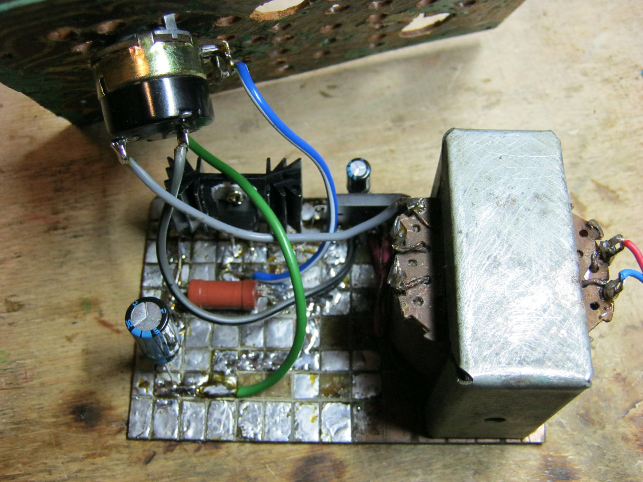
Planning to buy +249 Add to favorites I liked the review +160 +378Hello dear friends. In my next article, I decided to show how a power supply with voltage and current regulation was assembled. I saw the diagram in Aka’s video and decided to make myself the same device. There was no printed circuit board with the video, I drew it myself, it will be below. At first, I simply assembled the circuit using a surface-mounted installation, but for some reason it didn’t work for me the first time, I probably mixed up the transistor terminals, so I assembled it again, but now it just couldn’t help but work.
Here is a diagram of the device.
The circuit is quite simple and does not require adjustment; all the parts can be found in an old TV. But I didn’t disassemble the TV, since I had all these parts, well, let’s not deviate from the topic. I drew the PCB in the Sprint-Layout_5.0 program. and transferred it to the board.


But for some reason it didn’t go well for me and I had to finish drawing it with a permanent marker. Next I threw it into the etching solution.


When my board was etched, I washed it thoroughly with water; if you don’t wash it with water, it will be sticky. I dried it, removed the toner with a solvent and this is what happened.


The thing I don't like is drilling holes in the board. Now the most interesting and easy part begins - tinning the board.


After tinning, we need to remove everything that is left of the flux, let's do it with a solvent, just wipe our board. Now we take the parts, I found them in advance and insert them into the printed circuit board according to the diagram.


That's all, you can rejoice, the circuit is assembled. Here is the PCB


And also, in my photo there is no output capacitor, I didn’t install it because I couldn’t find it.
Here is the list of parts:
Two transistors kt818, kt815. Two electrolytic capacitors of 1000 microfarads (50-60 volts). Three fixed resistors at 820 ohm, 470 ohm, 24 k. Two variable resistors, the first from (4.7k-10k) and the second 84k. And one more diode 1N4007. The video will tell you the rest.
Here is another version of a laboratory power supply with a voltage from 0 to 30 V and adjustable current consumption of 0-2 A, which is always useful when a power supply is used to configure homemade circuits or when unknown devices are started for the first time.
IP circuit with current and voltage regulation

The power supply circuit itself is a popular set of the following elements:
- The adjustable stabilizer itself, in which T1 - BC337 is replaced with BD139, T2 - BD243 with BD911
- D1-D4 - 1N4001 diodes replaced with RL-207
- C1 - 1000 µF / 40 V replaced by 4700 µF / 50 V
- D6, D7 - 1N4148 to 1N4001
The transformer used has voltages of 25V, 2A and 12V, which is useful for controlling the fan that cools the radiator and power diodes on the panel. For this purpose, a small board was created with a bridge rectifier, filter capacitors and an LM7812 stabilizer (with a heatsink).

Inside the housing of the laboratory power supply there is a transformer, a board of the most regulated power supply, stabilizer boards - 12 V and 24 V, a radiator with a cooling fan (starts at 50 C).


On the front of the case there is a switch, three LEDs informing about the status of the power supply (220 V mains, fan on and protection - current limiting or short circuit), blue and red LED displays with a darkening film glued to them. Next to the displays are the control potentiometers, and to the right are the power leads. On the back of the case there is a power connector, a fuse and a 60x60mm cooling fan.

As for the indicator displays, they show:
- blue- current voltage in volts V
- red- current current in amperes A
The power source turned out to be really convenient and reliable. The entire assembly took several days. As for cooling, it turns on only under high load and then for a short time, about a couple of minutes.