The SWA and LSA antenna amplifiers are not independent devices, unlike external amplifiers such as Alcad. They are an electronic amplification board and require a power source and a protective casing.
used in grid-type antennas ASP-4, ASP-8, which are often called Polish antennas. The gain of such antennas without an amplifier is small, and its receiving properties are mainly determined by the installed amplifier.
SWA antenna amplifiers have an input impedance determined by the antenna design of 300 Ohms, an output impedance of 75 Ohms for connection to a television receiver, use a supply voltage from 9 V to 15 V and are designed to amplify frequencies 49 - 790 MHz.
amplifiers
What's happened grid antenna? Array antennas, sometimes called a grid antenna or a screen antenna, are a flat vibrator structure with a common mesh screen, which is a reflector. SWA antenna amplifiers are installed directly on such an antenna and are supplied with direct voltage via the antenna cable. Structurally, amplifiers for array antennas produced by various manufacturers are made the same, in the form of a small board measuring 60 x 40 mm with surface-mounted SMD elements.
amplifier swa installed in external antennas, grilles, meshes or, as they also say, “Polish antennas”. Depending on the distance to the transmitting television center, various amplifier board models are used, which have different gain coefficients and allow receiving television programs at a distance of 0 to 150 kilometers from the transmitter.
Antenna amplifiers characteristics
What parameters affect the quality of amplifiers? To evaluate the quality of the swa amplifier, that is, the quality of the image on the TV screen, the gain and noise figure parameters are very important. The noise figure should be as small as possible, and the gain should not be maximum; its value should be no more than that to bring the value of the signal arriving at the TV input into line with the norm.
The summary table shows the technical parameters and characteristics of antenna amplifiers swa, their modifications and analogues sym, lux, turbo, aws, wa, s&a, pa, gps, pae, ts. The noise figure and gain are given in dB, the recommended distance to the telecentre is in km.
| SWA amplifier board | Coefficient MV gain, dB |
Coefficient UHF gain, dB |
Coefficient noise, dB |
Range to telecentre, km |
|---|---|---|---|---|
| sym 01 | 0 | 0 | 0 | 0-10 |
| swa 1 | 2-5 | 8-14 | 2.8 | 3-10 |
| 1 lux | 13-14 | 13-23 | 2.7 | 5-15 |
| 2 | 15-18 | 20-25 | 2.8 | 10-20 |
| 3 | 2-6 | 20-28 | 3.1 | 10-30 |
| 4 lux | 0-8 | 29-35 | 3.0 | 20-45 |
| 5 | 5-10 | 25-31 | 3.1 | 10-40 |
| 6 | 5-10 | 25-30 | 3.1 | 10-40 |
| 7 | 5-6 | 25-32 | 3.0 | 30-70 |
| turbo 7 | 10-17 | 31-38 | 1.9 | 30-70 |
| 9 | 9-11 | 21-31 | 3.1 | 30-70 |
| 10 | 7-12 | 22-27 | 1.9 | 8-30 |
| 14 | 1-16 | 28-37 | 2.8 | 30-70 |
| 15 | 3-11 | 35-43 | 2.8 | 30-80 |
| 16 | 34 | 34 | 1.8 | |
| 17 | 11-15 | 35-42 | 2.9 | 30-100 |
| 18 | 32 | 38 | 1.8 | |
| 19 | 11-20 | 33-42 | 2.9 | 30-100 |
| 21 | 10 | 16 | 2.2 |
| SWA amplifier board | Coefficient MV gain, dB |
Coefficient UHF gain, dB |
Coefficient noise, dB |
Range to telecentre, km |
|---|---|---|---|---|
| 31 | 22 | 28 | 3.0 | |
| 41 | 30 | 33 | 1.5 | |
| swa 49 | 2-16 | 26-36 | 3.1 | 30-50 |
| 555 lux | 10-15 | 34-43 | 2.2 | 50-100 |
| 10-13 | 34-45 | 2.3 | 50-100 | |
| 999 | 10-13 | 33-45 | 2.9 | 80-120 |
| 5555 | 10-13 | 34-45 | 2.9 | 80-120 |
| 7777 | 4-13 | 34-45 | 2.8 | 100-120 |
| swa 9999 | 10-20 | 35-47 | 2.9 | 100-120 |
| 2000 | 13-18 | 40-47 | 2.8 | 100-130 |
| 3501 | 11-18 | 40-48 | 2.0 | 100-130 |
| swa 6000 | 20-52 | 50-52 | 1.2 | 80-140 |
| 9000 | 0-28 | 10-40 | 1.5 | 20-100 |
| 9001 | 12-16 | 42-45 | 1.5 | 100-150 |
| 9999 | 15-28 | 42-50 | 1.7 | 70-120 |
| aws 14 | 0-20 | 26-39 | 2.5 | 10-50 |
| 110 | 12 | 12 | 3.5 | |
| 120 | 22 | 22 | 3.9 | |
| 130 | 28 | 34 | 1.7 | |
| 140 | 28 | 34 | 1.7 | |
| pa 2 | 12 | 12 | 3.5 | |
| pa 5 | 28 | 34 | 1.7 | |
| pa 9 | 28 | 34 | 1.7 | |
| pa 10 | 22 | 22 | 3.9 | |
| gps wa-041 | 32 | 1.7 | ||
| gps wa-042 | 32 | 1.7 | ||
| gps wa-501s1 | 32 | 1.5 | ||
| gps wa-501s2 | 34 | 1.5 | ||
| gps wa-501s3 | 34 | 1.7 | ||
| pae-14 | 25 | 30 | 1.5 | |
| pae-42 | 25 | 30 | 2.5 | |
| pae-43 | 26 | 32 | 2.5 | |
| pae-44 | 26 | 32 | 2.7 | |
| pae-45 | 28 | 34 | 2.2 | |
| pae-65 | 24 | 28 | 2.5 | |
| pae-65ts | 24 | 28 | 1.7 |
Purpose of the LSA antenna amplifier
Antenna amplifiers LSA are produced for the repair of failed popular active television antennas Locus. Active antennas fail as a result of a powerful electromagnetic discharge during a lightning strike, a malfunction of the power adapter, due to aging of the elements, due to a violation of the sealing of the protective mounting box and wetness of the circuit elements.
Replacing the standard Locus amplifier with an lsa amplifier
Antenna amplifier LSA 417(LSA 020) is used to replace a failed amplifier of models L 025.09, L025.12, L025.62 and other Locus series 25 antenna models. Used for models manufactured after 2007. A characteristic feature is the presence of plastic guides in the amplifier mount. The Locus 025 series of antennas is equipped with one amplifier and one LSS-422 matching board, which has no active elements and which practically does not fail.
In older models of Locus L 025 antennas, LSA 417 amplifiers are used with a different method of mechanical fastening and do not differ in circuit design.
Antenna amplifier LSA 421(LSA-071) is designed for broadband amplification of television signals and is used in Locus L012.20, L023.09, L023.12, L024.09, L108.00 antennas.
The amplifier has a noise figure of no more than 2 dB, consumes a current of 20 mA from the power supply at a supply voltage of 12 V.
Antenna amplifier LSA 416 is used to replace indoor antennas Locus L405.05
In television antennas Locus 024.09 and Locus 024.12, instead of two LSA 419 amplifiers, an LSA 839 amplifier board is available.
Answers to questions about SWA and LSA amplifiers
How to properly connect a “Polish” antenna
Please tell me how to set up the TV and how to properly connect the Polish antenna (you need an amplifier). That’s why upon purchase it says that T2 is on the TV. But when setting up there is not a single channel. 12/14/2018, Ukraine, Dubensky district, village. Tarakanovo.
For the antenna to work, it is necessary to select the correct model of the SWA amplifier, attach it to the antenna and connect it to the network power supply through a separator. In addition, the antenna structure must be located at the point of best reception and directed towards the regional transmitting television tower.
Swa 49, which is good in terms of practical noise indicators.
Broadband antenna amplifier SWA- 555/LUX Eurosky installed in external antennas, grilles, meshes, or as they also say (Polish antennas), to amplify the TV signal. Depending on the distance to the television center, various models are used that have different amplification coefficients and allow receiving television programs at a distance from 0 to 150 km from the television center. Broadband antenna amplifiers S.W.A. have an input impedance determined by the antenna design of 300 Ohms, an output impedance of 75 Ohms, use a supply voltage from 9 V to 15 V and are designed to amplify the frequency range 49 MHz - 790 MHz. The voltage supply to the broadband amplifiers is carried out by adapters that differ only in the design of the housing and the output voltage is 12V. Broadband antenna amplifiers S.W.A. designed to increase the signal level and compensate for losses in transmission lines. Such amplifiers are produced using SMD technology using the most modern low-noise transistors, which are manufactured by leading foreign companies - ITT, Siemens, Philips, etc. They can be used in various designs of broadband antennas. Thanks to fully automated multiple monitoring, the broadband amplifiers have good reliability, and thanks to the protective coating, they are resistant to atmospheric agents.
Currently, the largest range consists of broadband antenna amplifiers SWA, WS, RA, RAE, GPS, etc. They have different circuit designs, which allows, through simple selection, to achieve the required results in areas with different levels of received signal. In areas with a relatively good level of received signal, amplifiers with one amplification stage (single-stage) SWA-1, SWA-1 /LUX, PA-2, S&A-110 are usually used. In areas with insufficient received signal level, use two-stage (two-stage) amplifiers WS-2, SWA-3, SWA-4/LUX, SWA-5 (SWA-6), SWA-7, SWA-8, SWA-9, PA- 5, S&A-130, PA-9, S&A-140, PA-10, S&A-120, PAE-14, PAE-42, PAE-43, PAE-44, PAE-45, PAE-65, PAE-65TS, WA-031, WA-032, WA-041, WA-042, WA501S-1.
The table shows the technical parameters and characteristics of antenna amplifiers S.W.A. and their analogues pa, gps, pae. The noise figure and gain are given in dB, the recommended distance to the telecentre is given in km.

Price for broadband antenna amplifier SWA-555/LUX Eurosky
Location of T2 transmitters in Ukraine.
The table provides information:
- Locations of T2 transmitters.
- average signal coverage radius.
- numbers of television channels of digital packages (multiplexes).
|
Transmitter location |
Average |
Digital packages |
|||||
|
Name |
Address |
TV channel numbers |
|||||
| Autonomous Republic of Crimea | |||||||
| Alupka | st. Lenina, 64 | ||||||
| Alushta | st. Sergeeva-Tsensky, 13 | ||||||
| Belogorsk | st. Nizhnegorskaya, 33a | ||||||
| Chapaevka | Sovetsky district | ||||||
| Dzhankoy | st. Extreme, 20 | ||||||
| Evpatoria | Razdolnenskoe highway, 17 | ||||||
| Feodosia | Simferopolskoe highway, 45a | ||||||
| Sevastopol | Cape Sarych (smt. Foros) | ||||||
| Annovka | Belogorsky district | ||||||
| Kerch | st. Ordzhonikidze, 144 | ||||||
| Kirovskoe | Chernomorsky district | ||||||
| Krasnoperekopsk | st. Tavricheskaya, 105 | ||||||
| Parthenite | st. Partenitskaya, 16a | ||||||
| Sevastopol | Ave. Pobedy, 96 (Vorontsova Gora) | ||||||
| Factory | Leninsky district | ||||||
| Zander | Vostochnoye highway, 33 | ||||||
| Simferopol | st. Studencheskaya, 14 | ||||||
| Yalta | Yuzhnoberezhnoe Highway, 55 | ||||||
| Vinnytsia region | |||||||
| Balanovka | Bershad district | ||||||
| Pogrebishche | st. Kotsyubynskogo, 23 | ||||||
| Vinnitsa | st. Maksimovicha, 23 | ||||||
| Volodymyrka | Shargorod district | ||||||
| Yampol | st. Chernyakhovsky, 2 | ||||||
| Volyn region | |||||||
| Gorokhov | st. Vatutina, 30a | ||||||
| Kovel | st. Varshavskaya, 5 | ||||||
| Lyubeshov | st. Lesnaya, 3 | ||||||
| Podgaitsy | Lutsk district | ||||||
| Novovolynsk | st. Pionerskaya, 6 | ||||||
| Shatsk | st. 50 years of Victory, 1-b | ||||||
| Dnepropetrovsk region | |||||||
| Dnepropetrovsk | st. Television, 3 | ||||||
| Dmukhailovka | Magdalinovsky district | ||||||
| Krivoy Rog | st. Television, 8a | ||||||
| Mogilev | Tsarichansky district | ||||||
| Nikopol | st. Karl Liebknecht, 113a | ||||||
| Ordzhonikidze | st. Telmana, 11a | ||||||
| Eagles | Pokrovsky district | ||||||
| Pavlograd | st. Kharkovskaya, 17a | ||||||
| Pereshchepino | st. Shevchenka, 126-b | ||||||
| Nikolaevka | Petropavlovsky district | ||||||
| Volnogorsk | st. Lenina, 38-A | ||||||
| Yellow Waters | Lenin Square, 5 | ||||||
| Donetsk region | |||||||
| Kramatorsk | st. Kirova, 699-a (RTS Andreevka) | ||||||
| Artemovsk | st. Rosa Luxemburg, 54 | ||||||
| Donetsk | st. Infantry, 4a | ||||||
| Konstantinovka | st. Demeshchenko, 116 | ||||||
| Krasnoarmeysk | st. Dnepropetrovskaya, 1 | ||||||
| Mariupol | st. Klenovaya Balka, 3 | ||||||
| Torez | st. Chernyshevsky, 15 | ||||||
| Zhytomyr Oblast | |||||||
| Andreevka | Chernyakhovsky district | ||||||
| Berdichev | st. Lenina, 78 | ||||||
| Brusilov | st. Lermontova, 171 | ||||||
| Kozhukhovka | Korostensky district | ||||||
| Yurovka | Malinsky district | ||||||
| Novograd-Volynsky | st. Kuibysheva, 14 | ||||||
| Olevsk | st. Svyato-Nikolaevskaya, 146 | ||||||
| Oak Guy | Ovrutsky district | ||||||
| Kotlyarka | Popelnyansky district | ||||||
| Transcarpathian region | |||||||
| Khust | With. Rokosovo (Mount Tovsta) | ||||||
| Mukachevo | Mount Pavlova | ||||||
| Rakhiv | Mount Terentin | ||||||
| Svalyava | Mount Kichera | ||||||
| Uzhgorod | st. Krymskaya, 24a | ||||||
| Great Berezny | Mount Yavornik | ||||||
| Zaporozhye region | |||||||
| Berdyansk | st. Rudenka, 4-a | ||||||
| Kuibyshevo | st. Lenina, 1-v (RTS Kamysh Zarya) | ||||||
| Melitopol | Ave. B. Khmelnitsky, 88/4 | ||||||
| Orekhov | st. Stepnaya, 25 | ||||||
| Zaporozhye | st. Matrosova, 24-a | ||||||
| Ivano-Frankivsk region | |||||||
| Debeslavtsy | Kolomyia district | ||||||
| Malaya Turya | Dolinsky district | ||||||
| Ivano-Frankivsk | st. Chornovola, 19 | ||||||
| Mykulychyn | Yaremche City Council | ||||||
| Kyiv region | |||||||
| Berezan | st. Lenina, 37 | ||||||
| White church | st. Tarashchanskaya, 196 | ||||||
| Dybintsy | Boguslavsky district | ||||||
| Kagarlyk | RRS CTE URRT tower | ||||||
| Kyiv | st. Dorogozhitskaya, 10 | ||||||
| Volodarka | st. Mira, 221a | ||||||
| Kirovograd region | |||||||
| Kirovograd | st. Sadovaya, 88 | ||||||
| Novoarkhangelsk | Slavy street, 153 | ||||||
| Novomirgorod | st. Lenina, 2 | ||||||
| Novoukrainka | st. Metelkova, 53 | ||||||
| Alexandria | st. Pakhomenka, 2 | ||||||
| Installation | st. Pushkina, 43 | ||||||
| Lugansk region | |||||||
| Belovodsk | RTS tower | ||||||
| Chernukhino | Perevalsky district | ||||||
| Lugansk | st. Demekhina, 25 | ||||||
| Lisichansk | Ave. Lenina, 161a | ||||||
| Popasnaya | st. Pershotravneva, 152 | ||||||
| Rovenki | st. Vygonnaya, 22 | ||||||
| Starobelsk | With. Podgorovka, RTS | ||||||
| Pine | Svatovsky district | ||||||
| Zorinovka | Melovsky district | ||||||
| Lviv region | |||||||
| Brody | st. Green, 19 | ||||||
| Lviv | st. High Castle, 9 | ||||||
| New Razdol | lane Pridorozhny, 18 | ||||||
| Pidbuzh | Drogobitsky district | ||||||
| Nikolaevkskaya area | |||||||
| Bereznegovatoe | st. Sports, 30-A | ||||||
| Nikolaev | Lenina Ave., 24-r | ||||||
| New Bug | maid. Wide area, 10a | ||||||
| Pervomaisk | Podgorodnyanskoe highway, 13 | 59 | |||||
| Voznesensk | st. Timiryazeva, 175 | ||||||
| Odessa region | |||||||
| Viktorovka | Berezovsky district | ||||||
| Ishmael | st. Zheleznyakova, 260a | ||||||
| Kamenskoye | Artsizsky district | ||||||
| Westerners | Kotovsky district | ||||||
| Kovbasova Polyana | Savransky district | ||||||
| Nikolaevka | Ovidiopolsky district | ||||||
| Odessa | dor. Fontanskaya, 3 | ||||||
| Sarata | st. Melnichnaya, 1b | ||||||
| Zhovten | Shiryaevsky district | ||||||
| Poltava region | |||||||
| Gadyach | pl. Sobornaya, 65a | ||||||
| Comb | st. Gorodishchenskaya, 142 | ||||||
| Iskrovka | Chutovsky district | ||||||
| Kobelyaki | st. Poltavskaya, 29a | ||||||
| Krasnogorovka | Velikobagachansky district | ||||||
| Kremenchuk | st. Kerchenskaya, 7a | ||||||
| Lokhvitsa | st. Lenina, 104-a | ||||||
| Lubny | st. Grushevsky, 27 | ||||||
| Coppices | Zinkovsky district | ||||||
| Poltava | Pershotravnevy Ave., (Pervomaisky) 26a | ||||||
| Rovenskaya region | |||||||
| Antopol | Rivne district | ||||||
| Dubrovitsa | st. Zheleznodorozhnaya, 7-i | ||||||
| Kuznetsovsk | st. Khometskaya, 1 | ||||||
| Sumy region | |||||||
| Belopole | st. May 1, 15 | ||||||
| Ovlashi | Romensky district | ||||||
| Shostka | st. Korotchenko, 88 | ||||||
| Sumy | st. Skryabina, 3 | ||||||
| Trostyanets | st. Neskuchanskaya, 50 | ||||||
| Ternopil region | |||||||
| Berezhany | Zalissya st., 7 | ||||||
| Buchach | With. Pidzamochek | ||||||
| Gorishna Vygnanka | Chortkiv district | ||||||
| Kremenets | st. Osovitsa, 12 | ||||||
| Lozovaya | Ternopil district | ||||||
| Kharkov region | |||||||
| Raisin | st. Krutaya, 56 | ||||||
| Kharkiv | st. Derevianko, 1a | ||||||
| Kupyansk | st. Lenina, 87 | ||||||
| Lozovaya | st. Cooperative, 53A | ||||||
| Kegichevka | st. Kirova, 81 | ||||||
| Great Burluk | st. Decorative, 4 | ||||||
| Kherson region | |||||||
| Chaplinka | st. Lenina, 1 | ||||||
| Genichesk | st. Lenina, 87-V | ||||||
| Kherson | st. Perekopskaya, 5 | ||||||
| Novotroitskoe | st. Bezrodnogo, 116a | ||||||
| Nizhnye Serogozy | st. Shchorsa, 13 | ||||||
| Vasilyevka | Kakhovsky district | ||||||
| Khmelnitsky region | |||||||
| Belogorye | Belogorsky district | ||||||
| Khmelnitsky | Prospect Mira, 43 | ||||||
| Kulchievtsy | Kamenets-Podilsky district | ||||||
| Full | st. Lesi Ukrainki, 5A | ||||||
| Cherkasy region | |||||||
| Kamenka | st. Lenina, 1A | ||||||
| Beeches | Mankovsky district | ||||||
| Cherkasy | st. Palehi, 2 | ||||||
| Kanev | st. Kyiv, 27 | ||||||
| Korsun-Shevchenkovsky | st. Martsenyuka, 1a | ||||||
| Satanovka | Monastyrischensky district | ||||||
| Polyanetskoe | Uman district | ||||||
| Shpola | st. 40th anniversary of Victory, 11-a | ||||||
| Chernivtsi region | |||||||
| Chernivtsi | st. Biletskaya, 6 | ||||||
| Novodnistrovsk | block 27, building. 5 | ||||||
| Chernihiv region | |||||||
| Tinitsa | Bakhmatsky district | ||||||
| Bobrovitsa | st. Dzerzhinsky, 113 | ||||||
| Chernigov | st. Komsomolskaya, 53B | ||||||
| Hills | Koryukivsky district | ||||||
| Nizhyn | lane Urozhainy, 8a | ||||||
| Bileshchyna | Prilutsky district | ||||||
Digital television of the DVB-T2 standard in Ukraine.
Until June 17, 2015, in accordance with the international agreement (Geneva 2006), Ukraine is obliged to switch completely to digital broadcasting of the DVB-T standard and DVB-T2. This is the plan for the development of the national television and radio information space. Now our country is beginning to gradually switch off broadcasting in analogue format. For quite a long time in Ukraine they have been broadcasting in test mode DVB-T and DVB-T2 digital standards. Standard DVB-T2 becomes the basis for broadcasting and development of digital television in Ukraine.
DVB-T2 This is the second generation European terrestrial standard for digital terrestrial television. Ether is a hypothetical all-pervasive medium (the upper layer of air). Unlike the first generation DVB-T standard, the standard DVB-T2 designed to increase network capacity by 30-50% while preserving core infrastructure and frequency resources.
In addition, among the benefits of switching to DVB-T2 the following can be distinguished:
- increasing the number of channels in the broadcast package.
- possibility of organizing regional (local) broadcasting.
- possibility of developing high definition television.
- release of ethereal frequencies.
- Available in all corners of Ukraine (covers 95% of the territory)
- Very easy to connect
- Excellent picture and sound quality
- All popular national TV channels are available
- Provided without subscription fee
Digital TV format DVB-T2- the most modern of all existing today, which, of course, the whole world will come to in the near future, since its capabilities are much wider than those of standard DVB-T. The main and undeniable advantage of the technology DVB-T2 is that its functionality is not limited to broadcasting free digital TV channels. In addition to watching 32 digital TV channels in the highest quality, in the near future it will be possible to record your favorite programs for delayed viewing, order movies from network servers, watch online television, and listen to digital radio. IN DVB-T2 the possibility of transmitting several independent traffic flows of different nature and structure is incorporated. Each digital stream is placed in its own main stream - the so-called PLP physical layer channel. For this purpose, a function for preprocessing input data has been introduced. Standard DVB-T2 fundamentally different in both system level architecture and physical layer properties, as a result of which DVB-T receivers are incompatible with DVB-T2.
DVB-T2 characteristics:
- OFDM modulation with OPSK, 16-QAM, 64-QAM or 256-QAM groups.
- OFDM modes 1k, 2k, 4k, 8k, 16k, 32k and “32k ext”. The symbol length for 32k mode is about 4ms.
- Relative lengths of guard intervals: 1/128, 1/32, 1/16, 19/256, 1/8, 19/128 and 1/4. (For 32k mode maximum 1/8).
- Forward error correction (FEC) with cascaded application of LDPC and BCH correction codes (as in DVB-S2 and DVB-C2).
- DVB-T2 supports channel frequency bands: 1.7, 5, 6, 7, 8 and 10 MHz. Moreover, 1.7 MHz is intended for mobile television.
- transmission in MISO mode using the Alamouti circuit, that is, the receiver processes the signal from two transmitting antennas.
DVB-T2 service capabilities:
- Multichannel multiplexing.
- Standard definition television SDTV in screen formats 4:3 and 16:9.
- Standard definition television HDTV.
- Ultra high definition television UHDTV.
- 3D television in the DVB 3D-TV standard.
- Interactive hybrid television in the Hbb TV standard.
- Video on demand.
- Teletext.
- TV guide.
- Subtitles.
- Stereo sound.
- Dolby Digital sound.
- Surround sound.
- Multisound (choice of broadcast language).
- Digital radio.
- Synchronize time and date with digital television broadcasts.
- Data transmission in the DVB-DATA standard.
- Forward and reverse communication channels for interactive services in the DVB-RCS and DVB-RCT standards.
- Broadband Internet access.
- Notification system.
Reception of DVB-T2 digital signal:
Reception of the digital signal is carried out by an on-air collective or individual (outdoor or indoor) television antenna, UHF, connected to various receivers:
- LCD/LED TV with built-in DVB-T2 tuner.
- TV set-top box (receiver, tuner, receiver) DVB-T2.
- DVB-T2 TV tuner for computer.
Advantage of digital signal DVB-T2 consists in the fact that a digital television signal is received by a UHF antenna and transmitted without distortion, as a result of which the stability of image and sound on TV receivers increases. Another advantage is the absence of image interference associated with atmospheric phenomena. The digital signal is protected from this, and on the TV screen you see a picture of very good quality. In addition to high-quality pictures, you get five-channel sound. Plus, you receive additional information EPG (electronic TV program) - provides information about the current program, and a TV guide for 7 days. The broadcast is broadcast in multi-channel networks consisting of five multiplexes, these include: 32 standard channels DVB-T2(MPEG-4), taking into account 28 national and 4 regional television channels. Further plans include a significant expansion of the number of television channels through paid channels; one way or another, 32 channels remain available without any subscription fee.
Now in digital standard DVB-T2 in Ukraine, 32 TV channels are available to viewers .
|
Digital plastic bag |
TV channel |
Logo |
Short description |
Note |
|
Inter |
TV channel "Inter" is a national channel. On Ukrainian air since October 1996. All this time, the channel has actually been the leader of domestic television. Inter took such positions thanks to strict adherence to the initially chosen concept of a family channel, taking into account the needs of all social and age groups of the population. |
HD* |
||
| Entertainment and information programs. The newest and best films and TV series. Daily talk show. The TV channel "Ukraine" covers all segments of the population. Broadcasting informational, educational, children's, entertainment, artistic, sports. |
HD |
|||
| One of the leaders of Ukrainian television. TV shows and movies, news and sports, series and entertainment programs. Everything is at the highest level. Everything for all of Ukraine. Everything is bright, high quality and relevant. |
|
|||
| "NTN" is a young all-Ukrainian information channel. The motto of the channel’s information service is “News Now.” In general, six hours of hot information product, including economic and political news from Ukraine and the regions, around the clock. The selection of films is aimed at audiences of different ages. Viewers are presented with masterpieces of world cinema, domestic and foreign television series. |
|
|||
| “K1” is a national innovative channel, universal in genre content. The channel's programming policy is its own production of programs that meet the highest professional standards and expectations of the modern audience. |
|
|||
| National broadcast channel. Information and journalistic programs, feature films for the whole family, youth, children's and sports programs. This is a television program for a wide variety of segments of the population and age categories. |
|
|||
| News and films, current information and entertainment. Everything that can be used daily and have fun while watching TV: cars, health, fashion, beauty, cooking, travel, a cozy home, interesting people. And smile, and laugh, and listen, and find out. The first non-state all-Ukrainian channel ICTV features long-familiar faces and fresh new facts. |
|
|||
|
Enter-film |
The film channel broadcasts films and programs about cinema for the whole family and for youth audiences. The broadcast schedule includes a special film screening for night owls. “Enter-film” in its program policy tries to take into account the tastes and preferences of the widest audience as much as possible. Films that have won awards at various film festivals are shown quite often. |
|
||
| The channel is addressed mainly to women who live in big cities, offering programs about modern lifestyle, hobbies, harmonious relationships between people and the daily needs of city residents. The Indigo TV channel shows viewers how to find harmony and happiness; viewers can learn to appreciate beauty and feel the taste of life. | ||||
| |
The hottest hits and the latest gossip, live interviews with stars and the latest events straight from the music venues. In order not to fall out, not to miss, to find out, to see for yourself, you need to watch ZOOM. Because ZOOM means “living in the world of music”! | |||
| "STB" is a Ukrainian television channel. The main viewer is a socially active person, so the program includes popular news, original music programs and films produced by foreign companies. |
|
|||
| Ukrainian TV channel, analogue of the Russian TV channel STS. The channel offers viewers programs of its own production and those produced by the STS channel, special projects and foreign entertainment programs, films, music. |
|
|||
| K2 TV channel is a real gift for women. Romantic series, films, talk shows, fashion shows will take you to the world of feelings, love, passion and beauty! The channel's light, emotional and cheerful style will make you forget about everyday problems, and besides, the channel will solve some of them for you. Without betraying its image and remaining faithful to its viewer, K2 offers a whole constellation of programs that will help good housewives cook deliciously, arrange a home, take care of children, while looking their best! K2 is a TV channel for women who strive to succeed in life. |
|
|||
|
New channel |
All-Ukrainian non-state channel with a large number of exclusive materials. Investigative reporting, live broadcasts, reality shows, discussions and considerations, TV series, movies and news. The channel's view of events in Ukraine and the world. Extraordinary materials, professionalism in presenting information. |
|
||
| Ukrainian music entertainment channel. Modern music of all genres sounds mixed with excellent Ukrainian shows about everything: about celebrities, musical events, hot hits, the latest conversations... About everything that is shown and what they don’t want to talk about... |
|
|||
|
Channel 5 |
“Channel 5” is an information channel. This is the latest news from politics and finance in Ukraine and the world, analytical programs, talk shows, current events in the world of sports, fashion and show business. Among the analytical programs are “Rush Hour”, “Closed Zone”, “5 kopecks”, “VIP Woman”, “5 Element”, “Greenwich Time”, etc. |
|
||
| “Mega” is the best entertaining, competitive and gaming program formats for those who strive to learn more about a person and his capabilities and are ready to challenge themselves and the world around them every day. |
HD |
|||
|
Pixel TV |
Pixel is the first and only Ukrainian TV channel for children. The channel's program content is based on high-quality educational, educational and educational programs for the youngest viewers. In particular, the best examples of world animation art, recognized developmental and educational projects, classics of domestic animation, as well as interactive projects of our own production that promote family and spiritual values and contribute to the comprehensive development of the child. |
HD |
||
| “XSPORT” positions itself as a sports channel that offers content for an audience with an active lifestyle and a healthy lifestyle. Along with classic sports - hockey, boxing, martial arts, athletics, tennis, swimming, handball, the channel offers its viewers programs about extreme sports, sport fishing, broadcasts of speedway competitions, "ecological" Formula E races, snooker, poker, educational and humorous programs related to sports. |
|
|||
|
UFO TV |
UFO TV is the coolest and most fashionable projects! “Comedy Club”, “Comedy Woman”, “Our Russia”, “Univer. New Dorm”, “Sasha + Tanya”, “Yak Gartuvavsya Style”, “High-Rise”, “Cities”, “Razdolbai”, “My First Car” and so on. These are all youth projects that have already caused a real sensation among viewers. Watch UFO TV - with us you are always in trend! |
|
||
| Ukrainian TV channel offering the best new films of world cinema for those who know how to feel, for those who know how to rejoice. Films for young people who live busy lives and expect just such an effect from cinema. |
|
|||
| |
DOBRO is a national Ukrainian TV channel filled with useful information and practical advice for the whole family; aimed at a female audience and at the same time interesting for the whole family. The TV channel creates a good mood, sets you up for family values, traditions and suggests ways to achieve life harmony. By turning on the Dobro TV channel, you are immersed in an atmosphere of home comfort and good mood. |
|
||
| The channel is known for its series of documentaries. In many ways, when it comes to documentary series, Tonys was and remains an innovator in this area of television. The channel also gives preference to popular domestic cinema. In addition, Tonis pays great attention to the purchase of foreign-produced films that are specifically intended for television screening. All channel products are divided by genre and topic, and the weekly schedule takes into account the tastes of different age groups. The TV program “Tonis” broadcasts such popular programs as: “Mister-class”, “Financier”, “Nerukhomist”, “TV Show”, “Theatre of the XXth Story”, “Context”, “Women’s Things”. Broadcasting around the clock. |
HD |
|||
|
Business |
|
Business - information and analytical business television channel. The TV channel systematically monitors and analyzes how effective state regulation of the Ukrainian economy is, how beneficial or harmful the decisions of the authorities are for certain sectors of domestic business. |
|
|
|
Espreso TV |
The central place on the channel is occupied by news of Ukrainian political, economic, social, cultural and sports life, as well as reports on events taking place abroad. |
|
||
|
Bank-TV |
Bank-TV will air banking and financial information, economic analytics, reviews of the business press, original programs, programs of central banks of other countries, information from international news agencies (for example, Bloomberg). |
HD |
||
| |
The broadcast of the Vintage TV channel is designed for lovers of old, even very old cinema. Here you will see films and performances shot back in the 1920s-1950s, meet such legendary actors as Faina Ranevskaya, Alexey Gribov, Erast Garin and many others. We invite all cinema connoisseurs to watch “Vintage TV” and enjoy the brilliant performances of the masters scenes from the first half of the twentieth century! |
|
||
| |
The TV channel “Eskulap TB” is addressed to everyone who is interested in a healthy lifestyle and wants to know more about health and medicine. On “Eskulap TV” you will see informational, educational and scientific programs on medical topics, as well as popular science films about the world around us, produced at one time by the famous studio “Kievnauchfilm”. Broadcasting of the channel “Eskulap TV” is carried out with the support of the Ministry of Health and National Academy of Medical Sciences of Ukraine. |
|
||
|
TV channel |
TV channel 112 Ukraine is one of the youngest, but already popular news channels. Broadcasting is in HD format. |
|||
|
regional |
||||
|
regional |
||||
|
regional |
* TV channels whose broadcasts are planned to be transferred to high definition format ( HD).
** Regional TV channels: differ depending on the region and the specific region.
![]()
The price of equipment for viewing in the DVB-T2 standard
In the article published here, our regular author analyzes the circuitry of Polish-made antenna amplifiers and justifies his informed approach to their selection in terms of noise and gain factors. He also gives recommendations for repairing such devices, which quite often fail from lightning discharges, and eliminating self-excitation. This will, we hope, allow many radio amateurs not only to choose the necessary amplifier, but also to improve its performance.
Active antennas from the Polish company ANPREL and some others have become widespread in Russia and the CIS countries. With insignificant self-gain, especially in the MB range, the parameters of such an antenna are largely determined by the antenna amplifier installed on it. This particular block is characterized by a number of disadvantages: it is prone to self-excitation, has a fairly high level of its own noise, is easily overloaded by powerful signals of the MB range, and is often damaged by lightning discharges. These problems are familiar to many owners of such antennas.
The issues of operating antenna amplifiers SWA and similar ones are extremely poorly covered in the literature. We can only note the publication, which indicates that the amplifier is overloaded with MB signals. Antenna owners have to deal with other shortcomings in a well-known way: by replacing amplifiers, choosing the best one. However, this method requires a lot of time and effort, since the amplifier is usually difficult to access - it is located along with the antenna on a high mast.
Based on an analysis of circuit design, my own experience and some materials from ANPREL, I propose a more informed approach to the selection of amplifiers, as well as a repair method that allows you to restore a damaged unit, and in some cases, improve its parameters.
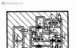
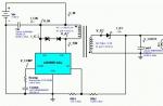
The market is filled with many interchangeable models of antenna amplifiers produced by ANPREL, TELTAD and others under different brands and numbers. Despite this diversity, most of them are assembled according to a standard circuit and are a two-stage aperiodic amplifier based on microwave bipolar transistors connected according to an OE circuit. To confirm this, let's look at models from different companies: a simple amplifier SWA-36 from TELTAD, the circuit diagram of which is shown in Fig. 1

and the common amplifier SWA-49 (analogue of SWA-9) from ANPREL - Fig. 2.

The SWA-36 amplifier contains two broadband amplification stages based on transistors VT1 and VT2. The signal from the antenna, through a matching transformer (not shown in the diagram) and capacitor C1, goes to the base of transistor VT1, connected according to the OE circuit. The operating point of the transistor is set by the bias voltage determined by resistor R1. The negative voltage feedback (NFF) operating in this case linearizes the characteristic of the first stage, stabilizes the position of the operating point, but slightly reduces its gain. There is no frequency correction in the first stage.
The second stage is also made on a transistor according to the circuit with OE and with voltage feedback through resistors R2 and R3, but also has a current feedback through resistor R4 in the emitter circuit, which rigidly stabilizes the mode of transistor VT2. To avoid a large loss of gain, resistor R4 is shunted to alternating current by capacitor SZ, the capacitance of which is chosen to be relatively small (10 pF). As a result, at the lower frequencies of the range, the capacitance of the SZ capacitor turns out to be significant and the resulting negative feedback on alternating current reduces the gain, thereby correcting the frequency response of the amplifier.
The disadvantages of the SWA-36 amplifier include passive losses in the output circuit on resistor R5, which is connected so that both the constant supply voltage and the signal voltage drop across it.
The SWA-49 amplifier is built similarly (Fig. 2), which also has two stages assembled according to a circuit with an OE. It differs from the SWA-36 in better isolation of the power supply circuits through L-shaped filters L1C6, R5C4 and an increased gain due to the presence of capacitor C5 in the OOS circuit (R3C5R6) of the second stage and transition capacitor C7 at the output.
Similar circuitry is inherent in most other SWA amplifiers (see, for example, the SWA-3 amplifier circuit shown in). Minor differences are most often found in the second stage, which can be equipped with different frequency correction circuits, have different OOS depth and, accordingly, gain. For some models, for example SWA-7, the first and second stages have a direct connection - the collector output of transistor VT1 is connected directly to the base output of transistor VT2. This allows both stages to be covered by the DC feedback loop and thereby improves the thermal stability of the amplifier.
In cascades based on transistors connected according to a circuit with an OE, the influence of internal connections and transition capacitances of transistors is greatest. It manifests itself in the limitation of the bandwidth and the tendency of the amplifier to self-excitation, the probability of which is greater, the higher the gain. To evaluate it, the concept of stability threshold is known - the limiting value of the gain, above which the amplifier turns into a generator. Many high-gain SWA antenna amplifiers operate near the stability threshold, which explains their frequent self-excitation.
As measures to increase the stability of amplifiers, ANPREL uses different topologies of printed circuit boards (affecting the mounting capacity), surface and volume coils, chokes, etc. A more radical method: switching transistors in a cascode circuit with OE-OB - for some reason not used . With an unchanged switching circuit for transistors with OE-OE, to solve the problem of stability, the company prefers to produce regulated power supplies. By reducing its voltage, it is possible to eliminate self-excitation of the amplifier while maintaining sufficient gain.
The main parameters (noise figure Ksh and gain Ku) of the basic models of SWA amplifiers according to the ANPREL catalog are listed in table. 1.
Let's consider the relationship of the main parameters with the circuitry of amplifiers and their impact on the reception quality.
As is known, the gain at high frequencies in cascades with OE is critical to the parameters of the transistors used, especially to the cutoff frequency frp. SWA amplifiers use bipolar microwave transistors of the p-p-p structure, marked as T-67, less often - 415, which determine the maximum achievable gain Ku of a two-stage amplifier of about 40 dB. Of course, in such a wide operating frequency band, the gain does not remain constant - its changes reach 10... 15 dB due to the unevenness of the frequency response at higher frequencies of the range and correction at lower frequencies. At maximum values of the gain Ku it is difficult to ensure the stability of the amplifiers, therefore in a number of models it is limited to values of up to 10...30 dB, which in many cases is quite sufficient (see Table 1).

Contrary to popular belief, it should be noted that gain cannot be considered the main parameter of an antenna amplifier. After all, the TVs themselves have a very large reserve of their own gain, i.e. They have high sensitivity, limited by gain. Their sensitivity, limited by synchronization, is somewhat worse. And finally, the lowest is noise-limited sensitivity. Consequently, the factor determining long-range reception should be the level of intrinsic noise of the electronic path, and not the gain. In other words, the limitation of reception is primarily due to the influence of noise interference, and not due to a lack of signal amplification.
The influence of noise is assessed by the signal-to-noise ratio, the minimum value of which is taken to be 20. With this ratio, noise-limited sensitivity is determined, which is equal to the input signal voltage 20 times greater than the noise voltage.
For TVs of the third to fifth generations, the sensitivity limited by noise is 50... 100 µV. However, at a signal-to-noise ratio of 20, image quality is very poor and only large details are legible. To obtain a good quality image, you should apply a useful signal to the TV input that is approximately 5 times larger, i.e., provide a signal-to-noise ratio of about 100.
An antenna amplifier must increase the signal-to-noise ratio, and to do this it should amplify the signal, not the noise. But any electronic amplifier inevitably has its own noise, which increases along with the useful signal and worsens the signal-to-noise ratio. Therefore, the most important parameter of the antenna amplifier should be considered its noise figure Ksh. If it is not low enough, then increasing the gain is useless, since both signal and noise are amplified equally and their ratio does not improve. As a result, even with a sufficient signal level at the antenna input of the TV, the image will be affected by intense noise interference (the well-known “snow”).
For a unified assessment of the noise of a multi-stage path, there is an indicator of the noise figure Ksh reduced to the input, which is equal to the noise level at the output divided by the total gain, i.e. Ksh = Ksh.out/Ku. Since the output noise level Ksh.out depends to the greatest extent on the noise level of the first transistor, amplified by all subsequent stages, the noise of the remaining stages can be neglected. Then Ksh.out = Ksh1Ku, where Ksh is the noise factor of the first transistor. Consequently, we obtain Ksh = Ksh1, i.e. the reduced noise figure of the amplification path does not depend on the number of stages and the overall gain, but is equal only to the noise figure of the first transistor.
This leads to an important practical conclusion - the use of an antenna amplifier can give a positive result when the noise figure of the first transistor of the amplifier is less than the noise figure of the first stage of the TV. The channel selectors of fifth-generation TVs use the KP327A field-effect transistor with a noise figure of 4.5 dB at a frequency of 800 MHz [Z]. Therefore, in the first stage of the antenna amplifier a transistor with Ksh1 should operate<4,5 дБ на той же частоте. Причем, чем меньше это значение по сравнению с коэффициентом Кш1 телевизора, тем эффективнее применение усилителя и тем выше качество приема.
The noise figure also depends on the quality of matching at the amplifier input and the operating mode of the first transistor. For SWA amplifiers, the type of transistor VT1, its operating mode and the quality of matching determine the reduced coefficient Ksh = 1.7...3.1 dB (see Table 1).
From the above it is clear that choosing an antenna amplifier according to the principle - the higher the gain, the better - is incorrect. This is why many owners, when changing amplifiers, cannot achieve good results. The reason for this paradoxical, at first glance, fact is that the noise figure is, as a rule, unknown (it is not in the sales information of companies), and in fact it only differs slightly for many models with different amplifications (see Table 1 ). Increasing the gain with a constant noise figure does not provide a gain in the signal-to-noise ratio and, therefore, does not improve the quality of reception. A rare success is achieved only when a low noise amplifier comes across by chance.
Therefore, when choosing an antenna amplifier, you need to focus primarily on the minimum noise level. An amplifier with Ksh can be considered quite good<2 дБ. Из табл. 1 лучшими можно считать модели SWA-7, SWA-9, имеющие Кш=1,7 дБ. Информацию о коэффициенте шума новых усилителей можно найти в каталогах фирмы ANPREL или в сети Интернет.
As for the gain, it, of course, also matters, but not for maximum amplification of weak signals, but, first of all, to compensate for losses in the connecting cable, matching-branching devices, etc. Because of these losses If there is insufficient amplification, the signal level at the TV input may fall below the sensitivity threshold, limited by synchronization or even gain, making reception impossible. Therefore, to correctly select the gain, it is necessary to know the signal attenuation in the entire connecting path. And its approximate value is easy to calculate.
The linear attenuation of the signal in the common RK-75-4-11 cable is equal to 0.07 dB/m at the first to fifth, 0.13 dB/m at the sixth to twelfth and 0.25...0.37 dB/m at 21-60 th television channels. With a feeder length of 50 m, the attenuation on channels 21-60 will be 12.5...17.5 dB. If an industrial passive splitter is installed, it introduces additional losses at each of its outputs, the value of which is usually indicated on the housing.
By calculating the attenuation in the cable and adding to it the attenuation in the splitter (if there is one), the minimum gain of the antenna amplifier is obtained. A margin of 12...14 dB is added to it to amplify weak signals, which is necessary due to the low efficiency of broadband small-sized receiving antennas. Based on the obtained Ku value, the antenna amplifier is selected. The obtained gain value should not be much exceeded, as this increases the likelihood of self-excitation and overload of nearby stations with powerful signals.
Repair of antenna amplifiers mainly comes down to replacing active elements damaged by lightning discharges. It should be noted that the presence of a diode at the input in some models does not guarantee complete lightning protection: during a powerful atmospheric discharge, both the protective diode and, as a rule, both transistors break through.
SWA antenna amplifiers are assembled using automatic surface assembly technology using microelements, which requires care during repairs. Soldering should be done with a small-sized soldering iron with a sharp tip. With the amplifier not working, you should carefully, trying not to damage the thin printed conductors, remove microtransistors VT1, VT2 and the protective diode (if any).
The main parameters of domestic transistors suitable for installation in SWA amplifiers are listed in table. 2 [Z]. It follows from it that the use of transistors KT391A-2, KT3101A-2, KT3115A-2, KT3115B-2, KT3115V-2 in the first stage does not worsen the noise characteristics of most amplifier models, and the use of transistors 2T3124A-2, 2T3124B-2, 2T3124V- 2, KT3132A-2 reduces Ksh to 1.5 dB, which improves the amplifier parameters. This circumstance allows us to recommend replacing the first transistor of the amplifier with the last ones indicated, even in serviceable but “noisy” amplifiers in order to improve the quality of their operation. It should be noted that in table. 2 gives the limit values, but typical parameters are, as a rule, better [3]. 
Low-noise microwave transistors of the 2T3124, KT3132 series are relatively expensive and low-current, so it is better to install them only in the first stage, and in the second use cheaper and more powerful transistors KT391A-2, KT3101A-2 (see Table 2) and even the KT371, KT372 series , KT382, KT399 and others with a cutoff frequency of about 2 GHz [Z]. However, in the latter case, the gain at the upper frequencies of the range will be slightly lower.
The housing dimensions of imported microtransistors are 1.2x2.8 mm with a lead length of 1...1.5 mm. Accordingly, the distances on the board between the printed pads for the transistor outputs are small. Installation of domestic transistors with a case diameter of 2 mm on the surface-mount side, although possible, is difficult: they can be damaged when soldering. It is better to install new transistors on the opposite side of the board, having previously drilled holes for the leads with a drill with a diameter of 0.5...0.8 mm. It is better to drill not in the printed conductor itself, but so that the hole touches the edge of the pad. If there is a layer of foil on the side opposite the surface mounting, then the holes in it should be countersunk with a drill with a diameter of 2...2.5 mm (except for the hole for outputting the emitter of transistor VT1).
Then new transistors are installed so that the crystal holder or device body touches the board. If the leads protrude significantly from the other side, they should be bitten off after soldering. Microwave transistors are sensitive to static electricity, so appropriate protective measures should be taken when soldering. Soldering time - no more than 3 s [Z].
The protective diode does not need to be installed. The best protection against atmospheric electricity is good grounding of the antenna.
In SWA amplifiers, both transistors operate with a collector current of 10...12 mA. After replacement, such a current is acceptable for the second transistor (for example, KT3101A-2), but exceeds the permanently acceptable one for the first if transistors of the KT3115, KT3124 and KT3132A-2 series are installed (see Table 2). The collector current depends on the parameter h21e, according to which the transistors have a significant spread. Therefore, after installing a specific instance, it is necessary to set the operating point of transistor VT1. To do this, remove microresistor R1 and temporarily connect a tuning resistor (SPZ-23, SPZ-27, etc.) with a resistance of 68...100 kOhm instead. Before turning on the power, the resistor slider must be in the position of maximum resistance so as not to damage the transistor.
The amplifier is supplied with a voltage of 12 8 from the power supply and the voltage drop across resistor R2 is measured (see Fig. 1 and 2). By dividing the measured voltage by the resistance of resistor R2, the collector current is determined. By adjusting the resistance of the tuning resistor towards a decrease, a collector current of about 5 mA is achieved, which corresponds to the minimum noise according to the characteristics of the transistors [3]. At this point, the adjustment is completed and instead of a tuning resistor, a constant of the same resistance (MLT-0.125 or imported) is soldered in, having first shortened its terminals to a minimum.
After this, the printed circuit board and unpackaged transistors are covered with a layer of radio engineering varnish or compound. The appearance of the restored SWA-36 amplifier is shown in Fig. 3. It uses transistors (Fig. 3,a) 2T3124B-2 (VT1) and KT3101A-2 (VT2). Due to the simplest design of the amplifier, measures have been taken to eliminate self-excitation: a ferrite microring is placed on the collector terminal of transistor VT1 (it is used in the SK-M channel selectors of ZUSTST and 4USTST TVs). The collector current of transistor VT1 is set by resistor R1 (Fig. 3.6) with a nominal value of 51 kOhm (was 33 kOhm).
In the second stage, transistors of the KT372, KT399 series were tested, with which stability and sufficient gain were maintained. At the same time, the possibility of installing an additional capacitor CD with a capacity of 150 pF (Fig. 3.6), shunting resistor R5 (see Fig. 1), to increase the gain was tested. When installing a capacitor, self-excitation of the amplifier is eliminated by lowering the supply voltage.
In the basic version (with transistors 2T3124B-2 and KT3101A-2), the amplifier provided better reception quality than before the repair, which was visually assessed to be approximately the same as reception with the new SWA-9 amplifier.
LITERATURE
1. Tuzhilin S. Broadband UHF amplifier. - Radio, 1997, N 7, p. 15.
2. Nikitin V. Advice for fans of long-distance television reception. Collection: “To help the radio amateur”, vol. 103. - M.: DOSAAF, 1989.
3. Semiconductor devices. Low power transistors. Directory. Ed. A. V. Golomedova. - M.: Radio and Communications, 1989.
A. PAKHOMOV, Zernograd, Rostov region.
In the article published here, our regular author analyzes the circuitry of Polish-made antenna amplifiers and justifies his informed approach to their selection in terms of noise and gain factors. He also gives recommendations for repairing such devices, which quite often fail from lightning discharges, and eliminating self-excitation. This will hopefully allow many radio amateurs not only to choose the necessary amplifier, but also to improve its performance.
Active antennas from the Polish company ANPREL and some others have become widespread in Russia and the CIS countries. With insignificant self-gain, especially in the MB range, the parameters of such an antenna are largely determined by the antenna amplifier installed on it. This particular block is characterized by a number of disadvantages: it is prone to self-excitation, has a fairly high level of its own noise, is easily overloaded by powerful signals of the MB range, and is often damaged by lightning discharges. These problems are familiar to many owners of such antennas.
The issues of operating antenna amplifiers SWA and similar ones are extremely poorly covered in the literature. We can only note the publication, which indicates that the amplifier is overloaded with MB signals. Antenna owners have to deal with other shortcomings in a well-known way: by replacing amplifiers, choosing the best one. However, this method requires a lot of time and effort, since the amplifier is usually difficult to access - it is located along with the antenna on a high mast.
Based on an analysis of circuit design, my own experience and some materials from ANPREL, I propose a more informed approach to the selection of amplifiers, as well as a repair method that allows you to restore a damaged unit, and in some cases, improve its parameters.
The market is filled with many interchangeable models of antenna amplifiers produced by ANPREL, TELTAD and others under different brands and numbers. Despite this diversity, most of them are assembled according to a standard circuit and are a two-stage aperiodic amplifier based on microwave bipolar transistors connected according to an OE circuit. To confirm this, let's look at models from different companies: a simple amplifier SWA-36 from TELTAD, the circuit diagram of which is shown in Fig. 1, and the common amplifier SWA-49 (analogous to SWA-9) from ANPREL - Fig. 2.
The SWA-36 amplifier contains two broadband amplification stages based on transistors VT1 and VT2. The signal from the antenna, through a matching transformer (not shown in the diagram) and capacitor C1, goes to the base of transistor VT1, connected according to the OE circuit. The operating point of the transistor is set by the bias voltage determined by resistor R1. The negative voltage feedback (NFF) operating in this case linearizes the characteristic of the first stage, stabilizes the position of the operating point, but slightly reduces its gain. There is no frequency correction in the first stage.
The second stage is also made on a transistor according to the circuit with OE and with voltage feedback through resistors R2 and R3, but also has a current feedback through resistor R4 in the emitter circuit, which rigidly stabilizes the mode of transistor VT2. To avoid a large loss of gain, resistor R4 is shunted to alternating current by capacitor SZ, the capacitance of which is chosen to be relatively small (10 pF). As a result, at the lower frequencies of the range, the capacitance of the SZ capacitor turns out to be significant and the resulting negative feedback on alternating current reduces the gain, thereby correcting the frequency response of the amplifier.
The disadvantages of the SWA-36 amplifier include passive losses in the output circuit on resistor R5, which is connected so that both the constant supply voltage and the signal voltage drop across it.
The SWA-49 amplifier is built similarly (Fig. 2), which also has two stages assembled according to a circuit with an OE. It differs from the SWA-36 in better isolation of the power supply circuits through L-shaped filters L1C6, R5C4 and an increased gain due to the presence of capacitor C5 in the OOS circuit (R3C5R6) of the second stage and transition capacitor C7 at the output.
Similar circuitry is inherent in most other SWA amplifiers (see, for example, the SWA-3 amplifier circuit shown in). Minor differences are most often found in the second stage, which can be equipped with different frequency correction circuits, have different OOS depth and, accordingly, gain. For some models, for example SWA-7, the first and second stages have a direct connection - the collector output of transistor VT1 is connected directly to the base output of transistor VT2. This allows both stages to be covered by the DC feedback loop and thereby improves the thermal stability of the amplifier.
In cascades based on transistors connected according to a circuit with an OE, the influence of internal connections and transition capacitances of transistors is greatest. It manifests itself in the limitation of the bandwidth and the tendency of the amplifier to self-excitation, the probability of which is greater, the higher the gain. To evaluate it, the concept of stability threshold is known - the limiting value of the gain, above which the amplifier turns into a generator. Many high-gain SWA antenna amplifiers operate near the stability threshold, which explains their frequent self-excitation.
As measures to increase the stability of amplifiers, ANPREL uses different topologies of printed circuit boards (affecting the mounting capacitance), surface and volume coils, chokes, etc. A more radical method: switching transistors in a cascode circuit with OE-OB - for some reason not used . With an unchanged switching circuit for transistors with OE-OE, to solve the problem of stability, the company prefers to produce regulated power supplies. By reducing its voltage, it is possible to eliminate self-excitation of the amplifier while maintaining sufficient gain.
The main parameters (noise figure Ksh and gain Ku) of the basic models of SWA amplifiers according to the ANPREL catalog are listed in table. 1.
Let's consider the relationship of the main parameters with the circuitry of amplifiers and their impact on the reception quality.
As is known, the gain at high frequencies in cascades with OE is critical to the parameters of the transistors used, especially to the cutoff frequency frp. SWA amplifiers use bipolar microwave transistors of the p-p-p structure, labeled as T-67, less often - 415, which determine the maximum achievable gain Ku of a two-stage amplifier of about 40 dB. Of course, in such a wide operating frequency band, the gain does not remain constant - its changes reach 10... 15 dB due to the unevenness of the frequency response at higher frequencies of the range and correction at lower frequencies. At maximum values of the gain Ku it is difficult to ensure the stability of the amplifiers, therefore in a number of models it is limited to values of up to 10...30 dB, which in many cases is quite sufficient (see Table 1).

Contrary to popular belief, it should be noted that gain cannot be considered the main parameter of an antenna amplifier. After all, the TVs themselves have a very large reserve of their own gain, i.e. They have high sensitivity, limited by gain. Their sensitivity, limited by synchronization, is somewhat worse. And finally, the lowest is sensitivity limited by noise. Consequently, the factor determining long-range reception should be the level of intrinsic noise of the electronic path, and not the gain. In other words, the limitation of reception is primarily due to the influence of noise interference, and not due to a lack of signal amplification.
The influence of noise is assessed by the signal-to-noise ratio, the minimum value of which is taken to be 20. With this ratio, noise-limited sensitivity is determined, which is equal to the input signal voltage 20 times greater than the noise voltage.
For TVs of the third to fifth generations, the sensitivity limited by noise is 50... 100 µV. However, at a signal-to-noise ratio of 20, image quality is very poor and only large details are legible. To obtain a good quality image, you should apply a useful signal to the TV input that is approximately 5 times larger, i.e., provide a signal-to-noise ratio of about 100.
An antenna amplifier must increase the signal-to-noise ratio, and to do this it should amplify the signal, not the noise. But any electronic amplifier inevitably has its own noise, which increases along with the useful signal and worsens the signal-to-noise ratio. Therefore, the most important parameter of the antenna amplifier should be considered its noise figure Ksh. If it is not low enough, then increasing the gain is useless, since both signal and noise are amplified equally and their ratio does not improve. As a result, even with a sufficient signal level at the antenna input of the TV, the image will be affected by intense noise interference (the well-known “snow”).
For a unified assessment of the noise of a multi-stage path, there is an indicator of the noise figure Ksh reduced to the input, which is equal to the noise level at the output divided by the total gain, i.e. Ksh = Ksh.out/Ku. Since the output noise level Ksh.out depends to the greatest extent on the noise level of the first transistor, amplified by all subsequent stages, the noise of the remaining stages can be neglected. Then Ksh.out = Ksh1Ku, where Ksh is the noise factor of the first transistor. Consequently, we obtain Ksh = Ksh1, i.e. the reduced noise figure of the amplification path does not depend on the number of stages and the overall gain, but is equal only to the noise figure of the first transistor.
This leads to an important practical conclusion - the use of an antenna amplifier can give a positive result when the noise figure of the first transistor of the amplifier is less than the noise figure of the first stage of the TV. The channel selectors of fifth-generation TVs use the KP327A field-effect transistor with a noise figure of 4.5 dB at a frequency of 800 MHz [Z]. Therefore, in the first stage of the antenna amplifier a transistor with Ksh1 should operate<4,5 дБ на той же частоте. Причем, чем меньше это значение по сравнению с коэффициентом Кш1 телевизора, тем эффективнее применение усилителя и тем выше качество приема.
The noise figure also depends on the quality of matching at the amplifier input and the operating mode of the first transistor. For SWA amplifiers, the type of transistor VT1, its operating mode and the quality of matching determine the reduced coefficient Ksh = 1.7...3.1 dB (see Table 1).
From the above it is clear that choosing an antenna amplifier according to the principle - the higher the gain, the better - is incorrect. This is why many owners, when changing amplifiers, cannot achieve good results. The reason for this paradoxical, at first glance, fact is that the noise figure is, as a rule, unknown (it is not in the sales information of companies), and in fact it only differs slightly for many models with different amplifications (see Table 1 ). Increasing the gain with a constant noise figure does not provide a gain in the signal-to-noise ratio and, therefore, does not improve the quality of reception. A rare success is achieved only when a low noise amplifier comes across by chance.
Therefore, when choosing an antenna amplifier, you need to focus primarily on the minimum noise level. An amplifier with Ksh can be considered quite good<2 дБ. Из табл. 1 лучшими можно считать модели SWA-7, SWA-9, имеющие Кш=1,7 дБ. Информацию о коэффициенте шума новых усилителей можно найти в каталогах фирмы ANPREL или в сети Интернет.
As for the gain, it, of course, also matters, but not for maximum amplification of weak signals, but, first of all, to compensate for losses in the connecting cable, matching-branching devices, etc. Because of these losses If there is insufficient amplification, the signal level at the TV input may fall below the sensitivity threshold, limited by synchronization or even gain, making reception impossible. Therefore, to correctly select the gain, it is necessary to know the signal attenuation in the entire connecting path. And its approximate value is easy to calculate.
The linear attenuation of the signal in the common RK-75-4-11 cable is equal to 0.07 dB/m at the first to fifth, 0.13 dB/m at the sixth to twelfth and 0.25...0.37 dB/m at 21 -60th television channels. With a feeder length of 50 m, the attenuation on channels 21-60 will be 12.5...17.5 dB. If an industrial passive splitter is installed, it introduces additional losses at each of its outputs, the value of which is usually indicated on the housing.
By calculating the attenuation in the cable and adding to it the attenuation in the splitter (if there is one), the minimum gain of the antenna amplifier is obtained. A margin of 12...14 dB is added to it to amplify weak signals, which is necessary due to the low efficiency of broadband small-sized receiving antennas. Based on the obtained Ku value, the antenna amplifier is selected. The obtained gain value should not be much exceeded, as this increases the likelihood of self-excitation and overload of nearby stations with powerful signals.
Repair of antenna amplifiers mainly comes down to replacing active elements damaged by lightning discharges. It should be noted that the presence of a diode at the input in some models does not guarantee complete lightning protection: during a powerful atmospheric discharge, both the protective diode and, as a rule, both transistors break through.
SWA antenna amplifiers are assembled using automatic surface assembly technology using microelements, which requires care during repairs. Soldering should be done with a small-sized soldering iron with a sharp tip. With the amplifier not working, you should carefully, trying not to damage the thin printed conductors, remove microtransistors VT1, VT2 and the protective diode (if any).
The main parameters of domestic transistors suitable for installation in SWA amplifiers are listed in table. 2 [Z]. It follows from it that the use of transistors KT391A-2, KT3101A-2, KT3115A-2, KT3115B-2, KT3115V-2 in the first stage does not worsen the noise characteristics of most amplifier models, and the use of transistors 2T3124A-2, 2T3124B-2, 2T3124V- 2, KT3132A-2 reduces Ksh to 1.5 dB, which improves the amplifier parameters. This circumstance allows us to recommend replacing the first transistor of the amplifier with the last ones indicated, even in serviceable but “noisy” amplifiers in order to improve the quality of their operation. It should be noted that in table. 2 gives the limit values, but typical parameters are, as a rule, better [3].

Low-noise microwave transistors of the 2T3124, KT3132 series are relatively expensive and low-current, so it is better to install them only in the first stage, and in the second use cheaper and more powerful transistors KT391A-2, KT3101A-2 (see Table 2) and even the KT371, KT372 series , KT382, KT399 and others with a cutoff frequency of about 2 GHz [Z]. However, in the latter case, the gain at the upper frequencies of the range will be slightly lower.
The housing dimensions of imported microtransistors are 1.2x2.8 mm with a lead length of 1...1.5 mm. Accordingly, the distances on the board between the printed pads for the transistor outputs are small. Installation of domestic transistors with a case diameter of 2 mm on the surface-mount side, although possible, is difficult: they can be damaged when soldering. It is better to install new transistors on the opposite side of the board, having previously drilled holes for the leads with a drill with a diameter of 0.5...0.8 mm. It is better to drill not in the printed conductor itself, but so that the hole touches the edge of the pad. If there is a layer of foil on the side opposite the surface mounting, then the holes in it should be countersunk with a drill with a diameter of 2...2.5 mm (except for the hole for outputting the emitter of transistor VT1).
Then new transistors are installed so that the crystal holder or device body touches the board. If the leads protrude significantly from the other side, they should be bitten off after soldering. Microwave transistors are sensitive to static electricity, so appropriate protective measures should be taken when soldering. Soldering time - no more than 3 s [Z].
The protective diode does not need to be installed. The best protection against atmospheric electricity is good grounding of the antenna.
In SWA amplifiers, both transistors operate with a collector current of 10...12 mA. After replacement, such a current is acceptable for the second transistor (for example, KT3101A-2), but exceeds the permanently acceptable one for the first if transistors of the KT3115, KT3124 and KT3132A-2 series are installed (see Table 2). The collector current depends on the parameter h21e, according to which the transistors have a significant spread. Therefore, after installing a specific instance, it is necessary to set the operating point of transistor VT1. To do this, microresistor R1 is unsoldered and a tuning resistor (SPZ-23, SPZ-27, etc.) with a resistance of 68...100 kOhm is temporarily connected instead. Before turning on the power, the resistor slider must be in the position of maximum resistance so as not to damage the transistor.
The amplifier is supplied with a voltage of 12 8 from the power supply and the voltage drop across resistor R2 is measured (see Fig. 1 and 2). By dividing the measured voltage by the resistance of resistor R2, the collector current is determined. By adjusting the resistance of the tuning resistor towards a decrease, a collector current of about 5 mA is achieved, which corresponds to the minimum noise according to the characteristics of the transistors [3]. At this point, the adjustment is completed and instead of a tuning resistor, a constant of the same resistance (MLT-0.125 or imported) is soldered in, having first shortened its terminals to a minimum.
After this, the printed circuit board and unpackaged transistors are covered with a layer of radio engineering varnish or compound. The appearance of the restored SWA-36 amplifier is shown in Fig. 3. It uses transistors (Fig. 3,a) 2T3124B-2 (VT1) and KT3101A-2 (VT2). Due to the simplest design of the amplifier, measures have been taken to eliminate self-excitation: a ferrite microring is placed on the collector terminal of transistor VT1 (it is used in the SK-M channel selectors of ZUSTST and 4USTST TVs). The collector current of transistor VT1 is set by resistor R1 (Fig. 3.6) with a nominal value of 51 kOhm (was 33 kOhm).

Fig.3
In the second stage, transistors of the KT372, KT399 series were tested, with which stability and sufficient gain were maintained. At the same time, the possibility of installing an additional capacitor CD with a capacity of 150 pF (Fig. 3.6), shunting resistor R5 (see Fig. 1), to increase the gain was tested. When installing a capacitor, self-excitation of the amplifier is eliminated by lowering the supply voltage.
In the basic version (with transistors 2T3124B-2 and KT3101A-2), the amplifier provided better reception quality than before the repair, which was visually assessed to be approximately the same as reception with the new SWA-9 amplifier.
LITERATURE:
1. Tuzhilin S. Broadband UHF amplifier. - Radio, 1997, N 7, p. 15.
2. Nikitin V. Advice for fans of long-distance television reception. Collection: "To help the radio amateur", vol. 103. - M.: DOSAAF, 1989.
3. Semiconductor devices. Low power transistors. Directory. Ed. A. V. Golomedova. - M.: Radio and communication, 1989.
Radio 1-99
Usually buyers say - "Sell us the amplifier with the highest gain." This is a misconception and we usually give them the example of tea. If you pour one small spoon of sugar into an ordinary mug of tea, then to many this tea will not seem sweet or tasty. So let's add a lot of spoons of sugar and this tea will be impossible to drink. In a situation with tea, it will sound like it was oversweetened. Regarding the gain of the antenna amplifier, it is also necessary to adhere to the norm. Signal over-amplification- there is a lot of noise on the screen - this is bad
Based on the above reasoning, manufacturers produce a large number of amplifiers for one type of antenna. Experienced installers, knowing the reception conditions and the strength of the electromagnetic field, can install the amplifier that is needed the first time. Without instruments and experience, the amplifier is installed using the selection method.
|
Board type |
Antenna gain |
Noises |
Range from repeater |
|
| Channels 1 - 21 | Channels 21 - 68 | |||
| SYM-01 *
approval fee |
0 | 0 | 0 | 0 - 10 |
| SWA - 1 | 2 - 5 | 8 - 14 | 2.8 | 3 - 10 |
| SWA-1 Lux | 13 - 14 | 13 - 23 | 2.7 | 5 - 15 |
| SWA - 2 | 15 - 18.5 | 20 -25 | 2.8 | 10 - 20 |
| SWA - 3 | 2 -6 | 20.5 -28 | 3.1 | 10 -30 |
| SWA - 4 Lux | 0 -8 | 29 - 35 | 3.0 | 20 - 45 |
| SWA-5 | 5 - 10 | 25 - 31 | 3.1 | 10 - 40 |
| SWA-6 | 5 - 10 | 25 - 30 | 3.1 | 10 - 40 |
| SWA-7 | 5 - 6 | 25 - 32 | 3.0 | 30 - 70 |
| Turbo - 7 | 10 - 17 | 31 - 38 | 1.9 | 30 - 70 |
| SWA-9 | 9 - 11 | 21 - 31 | 3.1 | 30 - 70 |
| SWA - 10 | 7 - 12 | 22 - 27 | 1.9 | 8 - 30 |
| SWA-14 | 1 - 16 | 28 - 37 | 2.8 | 30 - 70 |
| SWA - 15 | 3 - 11 | 35 - 43 | 2.8 | 30 - 80 |
| SWA-17 | 11 - 15 | 35 - 42 | 2.9 | 30 - 100 |
| SWA - 19 | 11 - 20 | 33 - 42 | 2.9 | 30 - 100 |
| AS-49 | 2 - 16 | 26 - 36 | 3.1 | 30 - 50 |
| SWA - 555 Lux | 10 - 15 | 34 - 43 | 2.2 | 50 - 100 |
| SWA - 777 Lux | 10 - 13 | 34 - 45 | 2.3 | 50 - 100 |
| SWA - 999 | 10 - 13 | 33 - 45 | 2.9 | 80 - 120 |
| SWA-5555 | 10 - 13 | 34 - 45 | 2.9 | 80 - 120 |
| SWA-7777 | 4 - 13 | 34 - 45 | 2.8 | 100 -120 |
| SWA - 9999 | 10 - 20 | 35 - 47 | 2.9 | 100 - 120 |
| SWA - 2000 | 13 - 18 | 40 - 47 | 2.8 | 100 - 130 |
| SWA-3501 | 11 - 18 | 40 - 48 | 2.0 | 100 - 130 |
| SWA - 6000 ** | 20 - 52 | 50 - 52 | 1.2 | 80 - 140 |
| SWA - 9000 *** | 0 - 28 | 10 - 40 | 1.5 | 20 - 100 |
| SWA-9001 | 12 - 16 | 42 - 54 | 1.5 | 100 - 150 |
| SWA-9501 | 15 - 28 | 42 - 50 | 1.7 | 70 - 120 |
| AWS - 14 **** | 0 - 20 | 26 - 39 | 2.5 | 10 - 50 |
*
- the matching board does not have transistors and is a passive matching element. In every SWA amplifier, this element is present and is designed to match the wave impedances of the antenna and cable. It is a special transformer.
According to one of the laws of electrical engineering - maximum power is transmitted when the internal resistances of the signal source and consumer are equal. The characteristic impedance of the antenna is 300 ohms. The characteristic impedance of the antenna television cable is 75 ohms. The TV input has the same characteristic impedance according to the international standard. Therefore, for maximum signal transmission from the antenna to the cable, this element is used.
** - the amplifier has 6 transistors
*** - adjustable amplifier
**** - has the ability to connect an additional meter antenna.