Adjusting the speed of electric motors in modern electronic technology is achieved not by changing the supply voltage, as was done before, but by supplying current pulses of different durations to the electric motor. PWM, which has recently become very popular, is used for these purposes ( pulse width modulated) regulators. The circuit is universal - it also controls the engine speed, the brightness of the lamps, and the current in the charger.
PWM regulator circuit
The above diagram works great, attached.
![]()
Without altering the circuit, the voltage can be raised to 16 volts. Place the transistor depending on the load power.
![]()
![]()
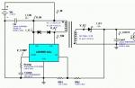
Can be assembled PWM regulator and according to this electrical circuit, with a conventional bipolar transistor:
![]()
And if necessary, instead of the composite transistor KT827, install a field-effect IRFZ44N, with resistor R1 - 47k. The polevik without a radiator does not heat up at a load of up to 7 amperes.
![]()
![]()
PWM controller operation
The timer on the NE555 chip monitors the voltage on capacitor C1, which is removed from the THR pin. As soon as it reaches the maximum, the internal transistor opens. Which shorts the DIS pin to ground. In this case, a logical zero appears at the OUT output. The capacitor begins to discharge through DIS and when the voltage on it becomes zero, the system will switch to the opposite state - at output 1, the transistor is closed. The capacitor begins to charge again and everything repeats again.
The charge of capacitor C1 follows the path: “R2->upper arm R1 ->D2”, and the discharge along the path: D1 -> lower arm R1 -> DIS. When we rotate the variable resistor R1, we change the ratio of the resistances of the upper and lower arms. Which, accordingly, changes the ratio of the pulse length to the pause. The frequency is set mainly by capacitor C1 and also depends slightly on the value of resistance R1. By changing the charge/discharge resistance ratio, we change the duty cycle. Resistor R3 ensures that the output is pulled to a high level - so there is an open-collector output. Which is not able to independently set a high level.
You can use any diodes, capacitors of approximately the same value as in the diagram. Deviations within one order of magnitude do not significantly affect the operation of the device. At 4.7 nanofarads set in C1, for example, the frequency drops to 18 kHz, but it is almost inaudible.
If after assembling the circuit the key control transistor gets hot, then most likely it does not open completely. That is, there is a large voltage drop across the transistor (it is partially open) and current flows through it. As a result, a lot of power is dissipated for heating. It is advisable to parallel the circuit at the output with large capacitors, otherwise it will sing and be poorly regulated. To avoid whistling, select C1, the whistling often comes from it. In general, the scope of application is very wide; its use as a brightness regulator for high-power LED lamps, LED strips and spotlights will be especially promising, but more on that next time. This article was written with the support of ear, ur5rnp, stalker68.
Another electronic device with wide application.
It is a powerful PWM (PWM) controller with smooth manual control. It operates at a constant voltage of 10-50V (it is better not to go beyond the range of 12-40V) and is suitable for regulating the power of various consumers (lamps, LEDs, motors, heaters) with a maximum current consumption of 40A.
Sent in a standard padded envelope 

The case is held together with latches that break easily, so open it carefully. 
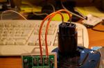
Inside the circuit board and the removed regulator knob 
The printed circuit board is double-sided fiberglass, soldering and installation are neat. Connection via a powerful terminal block. 

Ventilation slots in the case are ineffective, because... almost completely covered by the printed circuit board. 
When assembled it looks something like this 
The actual dimensions are slightly larger than stated: 123x55x40mm
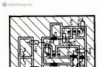
Schematic diagram of the device 
The declared PWM frequency is 12kHz. The actual frequency varies in the range of 12-13kHz when adjusting the output power.
If necessary, the PWM operating frequency can be reduced by soldering the desired capacitor in parallel with C5 (initial capacitance 1nF). It is not advisable to increase the frequency, because switching losses will increase.
The variable resistor has a built-in switch in the leftmost position that allows you to turn off the device. There is also a red LED on the board that lights up when the regulator is operating.
For some reason, the markings on the PWM controller chip have been carefully erased, although it’s easy to guess that it’s an analogue of NE555 :)
The regulation range is close to the stated 5-100%
Element CW1 looks like a current stabilizer in the diode body, but I’m not sure exactly...
As with most power regulators, regulation is carried out via the negative conductor. There is no short circuit protection.
There are initially no markings on the mosfets and diode assembly; they are located on individual radiators with thermal paste.
The regulator can operate on an inductive load, because At the output there is an assembly of protective Schottky diodes, which suppresses the self-induction EMF.
A test with a current of 20A showed that the radiators heat up slightly and can draw more, presumably up to 30A. The measured total resistance of the open channels of field workers is only 0.002 Ohm (drops 0.04V at a current of 20A).
If you reduce the PWM frequency, you will pull out all the declared 40A. Sorry I can't check...
You can draw your own conclusions, I liked the device :)
I'm planning to buy +56 Add to favorites I liked the review +38 +85Smooth engine operation, without jerks or power surges, is the key to its durability. To control these indicators, an electric motor speed controller is used for 220V, 12V and 24V; all of these frequencies can be made with your own hands or you can buy a ready-made unit.
Why do you need a speed controller?
An engine speed controller, a frequency converter, is a device with a powerful transistor, which is necessary to invert the voltage, as well as to ensure smooth stopping and starting of an asynchronous motor using PWM. PWM – wide-pulse control of electrical devices. It is used to create a specific sinusoid of alternating and direct current.
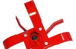
Photo - a powerful regulator for an asynchronous motorThe simplest example of a converter is a conventional voltage stabilizer. But the device under discussion has a much wider range of operation and power.
Frequency converters are used in any device that is powered by electrical energy. Governors provide extremely precise electrical motor control so that engine speed can be adjusted up or down, maintaining revs at the desired level, and protecting instruments from sudden revving. In this case, the electric motor uses only the energy needed to operate, instead of running it at full power.
 Photo – DC motor speed controller
 Why do you need a speed controller for an asynchronous electric motor:
- To save energy. By controlling the speed of the motor, the smoothness of its start and stop, strength and speed, you can achieve significant savings in personal funds. As an example, reducing speed by 20% can result in energy savings of 50%.
- The frequency converter can be used to control process temperature, pressure or without the use of a separate controller;
- No additional controller required for soft start;
- Maintenance costs are significantly reduced.
The device is often used for a welding machine (mainly for semi-automatic machines), an electric stove, a number of household appliances (vacuum cleaner, sewing machine, radio, washing machine), home heater, various ship models, etc.
Operating principle of the speed controller
The speed controller is a device consisting of the following three main subsystems:
- AC motor;
- Main drive controller;
- Drive and additional parts.
When the AC motor is started at full power, current is transferred with the full power of the load, this is repeated 7-8 times. This current bends the motor windings and generates heat that will be generated for a long time. This can significantly reduce engine longevity. In other words, the converter is a kind of step inverter that provides double energy conversion.
 Photo - diagram of the regulator for a commutator motor
 Depending on the incoming voltage, the frequency regulator of the speed of a three-phase or single-phase electric motor rectifies the current of 220 or 380 volts. This action is carried out using a rectifying diode, which is located at the energy input. Next, the current is filtered using capacitors. Next, PWM is generated, the electrical circuit is responsible for this. Now the windings of the induction motor are ready to transmit the pulse signal and integrate them into the desired sine wave. Even with a microelectric motor, these signals are issued, literally, in batches.
 Photo - sinusoid of normal operation of an electric motor
 How to choose a regulator
There are several characteristics by which you need to choose a speed controller for a car, machine electric motor, or household needs:
- Control type. For commutator motors, there are regulators with a vector or scalar control system. The former are more often used, but the latter are considered more reliable;
- Power. This is one of the most important factors for choosing an electrical frequency converter. It is necessary to select a frequency generator with a power that corresponds to the maximum permissible on the protected device. But for a low-voltage motor it is better to choose a regulator more powerful than the permissible watt value;
- Voltage. Naturally, everything here is individual, but if possible, you need to buy a speed controller for an electric motor, the circuit diagram of which has a wide range of permissible voltages;
- Frequency range. Frequency conversion is the main task of this device, so try to choose a model that will best suit your needs. Let's say, for a manual router, 1000 Hertz will be enough;
- According to other characteristics. This is the warranty period, the number of inputs, the size (there is a special attachment for desktop machines and hand tools).
At the same time, you also need to understand that there is a so-called universal rotation regulator. This is a frequency converter for brushless motors.
 Photo – regulator diagram for brushless motors
 There are two parts in this circuit - one is logical, where the microcontroller is located on the chip, and the second is power. Basically, such an electrical circuit is used for a powerful electric motor.
Video: electric motor speed controller with SHIRO V2
How to make a homemade engine speed controller
You can make a simple triac motor speed controller, its diagram is presented below, and the price consists only of parts sold in any electrical store.
To work, we need a powerful triac of the BT138-600 type, it is recommended by a radio engineering magazine.
 Photo - do-it-yourself speed controller diagram
 In the described circuit, the speed will be adjusted using potentiometer P1. Parameter P1 determines the phase of the incoming pulse signal, which in turn opens the triac. This scheme can be used both in field farming and at home. You can use this regulator for sewing machines, fans, tabletop drilling machines.
The principle of operation is simple: at the moment when the motor slows down a little, its inductance drops, and this increases the voltage in R2-P1 and C3, which in turn leads to a longer opening of the triac.
A thyristor feedback regulator works a little differently. It allows energy to flow back into the energy system, which is very economical and beneficial. This electronic device involves the inclusion of a powerful thyristor in the electrical circuit. His diagram looks like this:

Here, to supply direct current and rectify, a control signal generator, an amplifier, a thyristor, and a speed stabilization circuit are required.