When working with a power tool (electric drill, grinding device, etc.), it is desirable to be able to smoothly change its speed. But a simple decrease in the supply voltage leads to a decrease in the power developed by the tool. The proposed scheme (Fig. 1) uses feedback control of the motor current, as a result of which, as the load increases, the torque increases accordingly
On the shaft. The resistive-capacitive circuit R1-R2-C1 generates an adjustable reference voltage, which from the engine R2 enters the control electrode circuit of the thyristor VS1 and compensates for the residual back-EMF of the motor M1. If the engine rotation speed drops due to an increase in the load, its back-EMF also decreases . Due to this, in the next half-cycle of the mains voltage, the thyristor opens earlier due to the reference voltage. A corresponding increase in motor voltage leads to an increase in power at the motor shaft. When the speed increases and the load decreases, the described process occurs in reverse.

Setting up the device practically comes down to selecting resistance R1, so that at minimum speed the engine rotates smoothly, without jerking, and, at the same time, provides a full range of speed changes. It is possible that a small resistor will have to be connected to the lower terminal R2 in the circuit, limiting the minimum engine speed. If thyristor VS1 gets very hot, it needs to be installed on a heat sink.
A simplified version of the regulator is shown in Fig.. 2. If you clamp a screwdriver attachment into the chuck of an electric drill, you can use this attachment to tighten screws and self-tapping screws.
Literature
1 I. Semenov. Power regulator with feedback. - Radio Amateur, 1997, N12, P.21.
2 R.Graf. Electronic circuits 1300 examples - M Mir, 1989, P 395.
3. In Shcherbatyuk we drive the screws with an electric drill. - Radio Amateur, 1999 N9, S 23
An electric drill is now present in the tool kit of almost any craftsman, as it is an indispensable unit in everyday life or in the professional field. But, like any part, a drill can break, and in order not to contact specialists every time, you need to be able to maintain and repair your tool yourself. This article discusses signs of breakdown and options for eliminating them, as well as the most common malfunctions and how to repair a drill with your own hands.
A drill is an electric tool and performs the functions of drilling holes in various materials, as well as tightening screws. The work is carried out using special drills and tips that are inserted into the chuck.
An electric drill is equipped with a motor driven by a current of 220 Volts, which rotates the transmission gears and other components. The power of the power unit is adjusted by a special regulator, which is located on the start button and turns in both directions. Some models are equipped with a rotation axis switch, which changes the location of the brushes; from its drill chuck, the drill chuck can rotate both to the right and to the left.
There are two types of chuck: with a splined part and with a smooth part. In the first case, the drill is clamped with a special key, which, when turned, twists the lower part of the head and fixes the part. A regular smooth chuck can only be tightened by hand, so if you need to tighten the drill tightly, a chuck with splines has an advantage.
Main types of electric drill malfunction
Any tool can suddenly break down, this happens due to improper use, violation of maintenance regulations, or simply careless attitude towards equipment. In order to prevent breakdowns, you must follow all the rules established by the manufacturer, as well as timely repair and replace worn-out parts.
There are several types of possible malfunctions of a household electric drill, which include:
- When the start button is pressed, the drill does not operate. First of all, in this case it is necessary to check the quality of the contact between the plug and the socket, as well as the presence of electricity. Most often, such a malfunction occurs due to burnt contacts inside the plug or in the cord itself, when a wire break occurs as a result of a load or a change in current. This problem can be solved by simply replacing the lead cable;

- The drill chuck rotates, but the speed remains unchanged. Here we can assume that the drill speed controller is faulty, which may break due to mechanical deformation or dirt getting on the roller. There is a built-in contactor inside the regulator that can burn out, and it can only be repaired by replacing the entire assembly, since soldering such a small part at home will not work. In general, in a drill with a speed control mechanism, this is the most vulnerable part, so it must be treated with the utmost responsibility;
- When starting, an unpleasant burning smell appears from the brush vent, and the engine rotor sparks. The first thing you need to do is turn off the device and unplug the cord from the outlet, otherwise it will be much more difficult to repair the electric drill. Next, you need to carefully inspect the engine, determine the level of wear of the brushes and the rotor itself, and also check whether there are foreign objects or other contaminants inside that interfere with the rotation of the rod;

- Crunching sound in the central part of the instrument. All mechanisms and gears are hidden behind a plastic case, so you won’t be able to immediately identify the broken part. Most often, the splines of the drive disk break, especially in a drill with a hammer drill function, which, in addition to the usual transmission, has an impact mechanism and a locking device. To replace these elements, you will need to completely disassemble the instrument and carry out a detailed troubleshooting. It is important not to use a broken drill, since broken pieces can fall into other components, which, when rotated, will completely destroy the mechanism, and it will not be possible to restore it;

- The chuck does not secure the drill, the clamping blades do not converge when tightened with a wrench. Most often, this malfunction can be eliminated very quickly; the chuck itself is attached to the drill body with an ordinary screw, the head of which is located inside the head and can be unscrewed due to vibration. As a result, the bolt prevents the petals from tightening the drill; it must be tightened by inserting a shaped screwdriver;
- On an impact drill, the drill is inserted into a special chuck equipped with a quick-release mechanism; often pieces of metal or concrete get inside this unit, which get clogged into small cracks and do not allow the latch to fit into its socket, so the inserted chuck constantly pops out of the hole. Detailed cleaning of the instrument and removal of all contaminants will help here.

These malfunctions are the most common and often occur when using an electric drill at home. If more serious breakdowns occur, to restore the tool without errors, it is better to contact a service center, since without some experience and repair instructions it will not be possible to fix the breakdown.
Self-cleaning brushes and replacing them
During operation, especially in difficult conditions, plaque forms on the brushes, and the electric drill begins to heat up and spark. To repair a drill with your own hands, by replacing the brushes with new ones, you need to follow a certain algorithm of actions.
The first step is to unscrew the screws at the back of the electric motor. Most tool manufacturers, for ease of service, make this part in such a way that it can be quickly removed without disassembling the main body, and the start button remains in place. After unscrewing the cover, it is completely removed, making the motor brushes and its rotor accessible for maintenance.
Next, you need to disconnect the wire terminals from the carbon brushes and, bending the locking tabs, pull the element out. The power unit is equipped with two brushes on both sides, which wear out simultaneously and therefore must be replaced together. By the level of tip wear, you can understand the condition of the rotor bearings. If the wear is located in the upper or lower corner of the carbon rectangle, then we can conclude that there is play in the motor armature bearing; this part must also be replaced.
Before installing new drill brushes, you need to blow all internal elements with compressed air; this will help clean the rotor of dust and prevent the formation of plaque on the new parts. The button must also be cleaned so that its return spring can move freely. The brushes are inserted into the seat and secured with a lock, after which the terminals are connected and the cover is reassembled.
If it is necessary to replace the start button or speed controller, then it is possible to repair this unit only if there is a connection diagram for the drill button, which must be indicated in the operating instructions for the tool. The connection of all electrical parts and cables must be carried out in a de-energized area and only in accordance with the diagram.
Thus, when planning to repair an electric drill yourself, you need to acquire special literature and tools so that there is no doubt about the quality of the electrical connections when installing new spare parts.
Video
An electric drill is an indispensable assistant in all types of home repairs: it can be used to perform a number of tasks from mixing paints, wallpaper glue to its main purpose - drilling various holes. The product's power button wears out quickly and has to be repaired or replaced with a new one quite often. To carry out this rather simple operation, the user needs a drill button connection diagram and knowledge of the most common malfunctions of this important part.
This simple-looking device, during use, gives signals to the user that he will soon need repairs, but not everyone understands them. If the drill begins to work with temporary interruptions or the button requires pressing harder than before, then these are the first symptoms of incorrect operation of this part.
When you use a cordless drill, the first thing you need to do is measure the battery voltage with a tester - if it is less than the nominal value, then it needs to be charged.
In this case, we are especially interested in the condition and functionality of the product’s on/off button. It is quite simple to check that it is working properly: you need to unscrew the fastenings of the main body, remove the top cover and check the voltage of the wires going to the device by plugging the power cord into a power outlet. When the device shows voltage supply, but when you press the button the product does not work, this indicates that it is broken or there has been a problem. burning of contacts inside the device.
Regular on/off button
Repairing or replacing a drill button is considered a simple process, but you need to have certain skills - if you open the side wall carelessly, many parts can fly apart in different directions or fall out of the case.
As written above, the button may not function due to oxidation or burnt contacts. To fix this you need take it apart, observing the following order.
- Carefully unhook the protective cover latches and open it.
- Remove carbon deposits on the contacts with alcohol, or clean them with sandpaper.
- Then assemble and check.
If everything works fine, it means the reason was in the contacts, otherwise you need to button replacement.
You should know that the special layer that is applied under the rheostat slider during manufacturing often wears off - in this case the button also needs to be replaced.

Quite often, the drill button connection diagram is used to check the functionality of the entire structure: only if it is available, can partial repairs be made or the button be connected correctly if it is replaced. The diagram must come with product operating instructions, if for some reason it is not there, then you can search on the Internet.
Power button with reverse/speed control
The drill button shown in the photo, in addition to reverse, has a built-in electric motor speed controller. This design is highly complex, so it is not possible to disassemble it without special skills: as soon as you open the case, all the parts will “scatter” in different directions, because they are supported by springs. Without knowing their correct location, it will be impossible to put the entire structure back together - it’s easier to buy a new one and make the connection by checking a special diagram, which can be found on the Internet.

Modern drills are produced with reverse, so the button performs several functions at once:
- basic inclusion of the product in operation;
- adjusting the rotation speed of the electric motor;
- turning on reverse - changing the direction of rotation of the engine rotor.
Attention! The reverse control and speed controller are located in different housings - they must be checked separately.
It must be remembered that in modern products speed controller is located on a special substrate, and during manufacture it is filled with a compound - an insulating composition, which, after hardening, protects all parts from mechanical, temperature and chemical influences. Therefore, it cannot be repaired.

As can be seen from the connection diagram, when it contains a drill button along with reverse, the rotation is switched using special toggle switch. In this case, plus or minus is supplied to different brushes, so the motor armature rotates in different directions.
You should not disassemble the drill start button yourself if its design is complex - disconnect the wires and take it to a service center, where professional specialists will carry out a complete diagnosis and repair.

Our assistant can drill different materials, so there is often a lot of dust and waste. After each use you should clean the drill, then the next time you use the device, it will work like a Swiss watch: without failures or annoying stops.
One of the visitors from the Republic of Bashkortostan wrote to me about two weeks ago. He liked the circuit of an electronic speed controller for a micro drill on Radiokot, but it has several disadvantages: greater heat generation LM317 and a low maximum current of 1.5A. He suggested using the LM2596 module instead of LM317 to increase the output current to 3A.
The idea is good in concept, but I’ll tell you about how to adapt the module to the control circuit.
To begin with, I will propose a modified circuit by Alexander Savov on LM317
The meaning of this scheme is that when there is no load on the drill shaft, the engine speed is minimal, but as soon as it is loaded a little, the speed jumps to the maximum possible. All this is implemented using a current sensor on R6 and a comparing comporator with a threshold slightly higher than the drop on the shunt
I decided to try this scheme with a canopy and the scheme works quite well. The engine under load was used from a 12V screwdriver 

Using the same method on the current sensor, I redesigned the circuit for LM2596, slightly reworking the module and adding a Savov circuit to it. Here's what I got

I connected the module with the motor to 12V, set the trimmer resistor on the module to the minimum engine speed, approximate resistance 5kOhm. After the changeover, I unsoldered and installed a 5.1 kOhm resistor; in the diagram this resistor is indicated as R11. Now I installed a key on the fourth leg, shunting it to the ground. I connected a current detector to the key and began testing. I measured the drop on the R8R9 shunt, set the voltage on the 2nd leg with the R7 trimmer to a few millivolts more than on the 3rd leg. The circuit worked rather sluggishly, it took a long time to turn on, then it took a long time to turn off. By selecting a resistor in the feedback and C8, we were able to achieve stable operation.
This is what a mounted drill speed controller looks like 

In principle, the circuit turned out to be quite working and has the right to life, but we must take into account that LM358 must be powered from a stabilized voltage, so it is recommended to set it to .
I’m not going to implement a drill speed controller on a printed circuit board, I already have a machine, but I’ll print it for you a little later, I don’t have time right now
I would also like to note that the LM2596 module used was provided by a friend from Bashkortostan, he has a website SolBatCompany.Ru, selling solar panels and various electronic modules, I recommend checking it out. You can buy such a module in China for only 50 rubles, here is the link
Using the assembled speed controller, I made a short video of its operation.
For high-quality drilling of board holes, it is necessary to use an electric drill with a torque and speed stabilizer. The transistor stabilized unit has large power losses on the regulated transistor. The large weight and dimensions of the transformer and radiators do not allow for a portable version of the device.
Thyristor regulators voltages are distinguished by their low weight and technical capabilities for stabilizing the speed and torque of the electric motor. The voltage drop across the power thyristor in pulse mode is insignificant and at low power there is no need for a radiator.
Characteristics:
Mains voltage 220V
Power 300 Watt
Load current 10 Amps
Stabilization 86.7%
Regulator circuit speed of the electric drill stabilizes the torque by introducing positive feedback from the electric motor M1 through the RC circuit R12C2 VD2R6R1C1 to the emitter of the unijunction double-base transistor VT1
Diode VD2 allows you to supply only pulses of positive polarity from the brushes of the electric motor of the drill M1 to the emitter of transistor VT1. Variable resistor R6 works as a speed regulator, and at the same time stabilizes them when the load changes:
Without Feedback 0.6A 22.2 V 13 watts 260 rev. min
With Feedback 2.8 A 21 V 58.8 watts 520 rpm
With feedback, the speed drops slightly, at an idle speed of 600 rpm.
Characteristics of dual-base transistors:
|
Iе max, mA |
UB1B2 max, B |
UB2E max, B |
Pmax, mW |
RB1B2, kOm |
fmax, kHz |
||

Single-junction double-base transistors designed for operation in generators of periodic and single pulses. The resistance between the terminals of the transistors depends on the current of the control emitter junction. On the input current-voltage characteristic of unijunction transistors there is a section with a negative differential resistance. At a certain voltage at the emitter, the transistor is unlocked and the current through the base quickly increases. The process occurs like an avalanche.
The unijunction transistor belongs to the thyristor family. The unijunction transistor is included in the KU106A-G transistor-thyristor assembly and is a hybrid device consisting of a unijunction transistor and a triode thyristor.
Scheme:
The unlocking pulse from the unijunction transistor VT1 arrives at the control electrode of the thyristor VS1, which goes into a conducting state and remains in it as long as the forward current flowing through the thyristor VS1 is greater than the holding current.
The voltage from resistor R3 of the cathode circuit VS1 through resistors R7R9 is supplied to the control electrode of the powerful thyristor VS2 and brings it into the open state.
The switching threshold of thyristor VS2 is set by resistor R9. due to the wide spread of input characteristics. The anode of the power thyristor is directly connected to the electric motor of the M1 electric drill.
Pulses of negative polarity that occur during rotation of the electric motor are eliminated by diode VD3.
Part of the voltage from the motor collector is supplied to stabilize rotation - to the emitter of the dual-base transistor VT1.
The HL1 LED indicates the voltage on the electric drill motor and reduces impulse noise with voltages of more than 300 Volts.
Diode VD3 ensures the flow of reverse current to the armature of the electric motor while the thyristor is locked. At the beginning of each half-cycle, the rectifier voltage through diode VD2 and resistors R1, R6 is supplied to charge capacitor C1; there is still no back emf at this moment. Next, the voltage at the anode of the thyristor VS2 will be equal to the difference in the voltage of the diode bridge VD4-VD7 and the back emf of the armature, that is, from the rotation speed.
Reducing the speed with increasing load torque on the shaft reduces the back-emf and speeds up the charging of capacitor C1, reduces the delay angle of the thyristor unlocking - the decrease in speed is almost completely compensated.
Voltage pulses from resistor R3 are supplied to the control electrode of low-power thyristor VS1 for pre-amplification, then through resistors for setting the switching threshold R7, R9
to the control electrode of the powerful power thyristor VS2. Circuit VD1, R9 reduces the influence of mains voltage and load on the operation of the relaxation generator on transistor VT1.
The current of thyristor VS1 is limited by the value of resistor R4; it is not recommended to reduce its value, since the restoration of controllability will be impaired, that is, the interval between the transition of the thyristor current and voltage through zero to negative polarity and back to positive will decrease.
The recovery time depends on many factors: forward and reverse current, the amplitude of the switched-off voltage and the voltage on the control electrode.
By the way, radio interference is created by a reverse current, which almost instantly drops at the stage of turning off the thyristor at a very high speed and can cause overvoltages.
Forced switching is created by installing a diode VD3 and allows you to interrupt the current in the thyristor VS2 for a time sufficient for blocking.
Practical tests of the electric drill speed controller in different modes with changes in the ratings of radio components confirmed the theoretical justification for using positive feedback to stabilize the speed and speed of the electric motor:
Idle speed did not exceed 600 rpm,
the load on the electric motor shaft in both cases was about 4 kg of force, electric motor type DPR 72-F6-06 DC, body length 80 mm, diameter 40 mm.
The torque increased in the presence of feedback, the speed dropped slightly.
Radio components in the circuit not scarce:
resistors for a power of 0.25 watts of the MLT type, the double-base transistor VT1 and the thyristor VS1 can be replaced by the KU106V-G assembly, the type of power thyristor and transformer depends on the voltage and power of the electric motor used. Transformers of the TN-54 type with four windings of 6.3 volts and a current of more than three amperes, connected in a series circuit, work well in the circuit.
The silicon diode assembly type PBL405 has a low voltage drop and does not require a heatsink.
Install a small radiator 60*40*50 on the flat thyristor VS2.
Circuit adjustment The speed controller of an electric drill is as follows: at the minimum value of the resistance of resistor R6 (revolutions), set the threshold for turning on thyristor VS2 by changing the value of resistor R9, then by increasing the resistance of resistor R6, set the required electric motor speed.
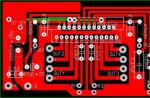
In the printed wiring diagram, almost all radio components are located except for the switching circuits, power transformer and diode bridge, the speed controller and LED indicator HL1 are installed on the top cover of the case, fuse FU1, switch SA1 and the power cord output are attached to the side.
Literature:
1. Thyristors. Technical reference 1971 Translation from English. Publishing house "Energy".
2. Electric drill speed regulator. V. Novikov. "Radiomir" No. 5 2006 p. 19
3. Resistors, capacitors, transformers, chokes, switching devices for electronic devices. Directory. Minsk "Belarus" 1994
List of radioelements
| Designation | Type | Denomination | Quantity | Note | Shop | My notepad |
|---|---|---|---|---|---|---|
| VT1 | Transistor | KT117B | 1 | To notepad | ||
| VS1 | Thyristor & Triac | KU101E | 1 | To notepad | ||
| VS2 | Thyristor & Triac | KU202E | 1 | To notepad | ||
| VD1 | Zener diode | D818B | 1 | To notepad | ||
| VD2 | Diode | KD503B | 1 | To notepad | ||
| VD3 | Rectifier diode | 1N4005 | 1 | To notepad | ||
| VD4-VD7 | Diode | PBL405 | 4 | To notepad | ||
| C1-C4 | Capacitor | 0.1 µF | 4 | To notepad | ||
| C5 | Capacitor | 0.05 µF 630 V | 1 | To notepad | ||
| R1 | Resistor | 4.7 kOhm | 1 | To notepad | ||
| R2 | Resistor | 910 Ohm | 1 | To notepad | ||
| R3, R12 | Resistor | 100 Ohm | 2 | To notepad | ||
| R4 | Resistor | 1.2 kOhm | 1 | To notepad | ||
| R5 | Resistor | 360 Ohm | 1 | To notepad | ||
| R6 | Variable resistor | 100 kOhm | 1 | To notepad | ||
| R7 | Resistor | 1.5 kOhm | 1 | To notepad | ||
| R8 | Resistor | 1 kOhm | 1 |